Cool, thanks!It was completely random George, but it seems a majority of the hotties were made by Bob's stoner brother when he was the transformer winder...in the Ser I's...
Some Ser II's like Darcy's were 108...

You are using an out of date browser. It may not display this or other websites correctly.
You should upgrade or use an alternative browser.
You should upgrade or use an alternative browser.
PL 700 Pro Build
- Thread starter George S.
- Start date
Skratch
Chief Journeyman
My 700B's run between 102 to 107 VDC
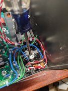
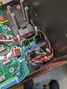
Only wiring issue I'm unsure about is the 4 fuse holders with the bent over base lugs. I assume B+ and B- are wired here to those shared lugs directly from the storage caps?
The blue wires at the tips go to B- connections on the back planes, the green to B+ on the back planes.
The blue wires at the tips go to B- connections on the back planes, the green to B+ on the back planes.
Attachments
- Joined
- Jan 14, 2011
- Messages
- 75,918
- Location
- Gillette, Wyo.
- Tagline
- Halfbiass...Electron Herder and Backass Woof
Yep, and Yep..
- Joined
- Jan 14, 2011
- Messages
- 75,918
- Location
- Gillette, Wyo.
- Tagline
- Halfbiass...Electron Herder and Backass Woof
If the blue and green wires are coming from the right caps, yes...
Thanks, that's good to know. Whole project would be at a stand still with a weak transformer!My 700B's run between 102 to 107 VDC
Righty lefty? Lee, I assume those B+ and B- fuse holder bases need supply voltage from the B+ and B- screw terminals on the storage caps. Being that they'll get the appropriate -102 VDC and + 102 VDC. Wasn't absolutely sure, thought I'd better askIf the blue and green wires are coming from the right caps, yes...
- Joined
- Jan 14, 2011
- Messages
- 75,918
- Location
- Gillette, Wyo.
- Tagline
- Halfbiass...Electron Herder and Backass Woof
Not a problem George....
- Joined
- Jan 14, 2011
- Messages
- 75,918
- Location
- Gillette, Wyo.
- Tagline
- Halfbiass...Electron Herder and Backass Woof
Yep...
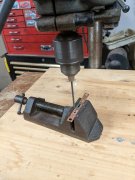
Well this is all for today. Need to drill a couple holes in the busbar for the extra grounds. The long candy cane colored loop will be cut and soldered to the on off switch once the amp checks out. Much more work to wiring a 700 compared to a 400.
Attachments

Last edited:
For you guys who haven't built these before, the copper bus bar needs extra holes drilled in it for the extra ground wires. The transformers secondary center tap which is a stranded black wire on the dual primary transformers, solders in here along with additional ground wires. I'll shine it up with some fine grit sandpaper so it'll solder nicely, then use a higher wattage gun and a little rosin paste flux.
Attachments
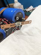
The screwdriver is pointed at the one and only one chassis ground these amps are supposed to have, the "star ground". The buss bar is also often called the star ground. A Weller Expert 140 watt gun was used for soldering the buss bar, along with a little Radio Shack rosin paste flux. Seen a few photos of builds with cold joints on the bus bar.
Additional ground wires will be installed for the WOAD Cylon meters and Watts Abundant DC Protect board.
Additional ground wires will be installed for the WOAD Cylon meters and Watts Abundant DC Protect board.
Attachments
Last edited:
J!m
Veteran and General Yakker
(I don't know so, keep that in mind)
If that is the single return for the amp, is the wire size heavy enough to return all the power that is supplied to it? Based on the potential of the little welders, I would expect a single return line to be quite beefy indeed. Maybe a 12ga line? I don't know.
If that is the single return for the amp, is the wire size heavy enough to return all the power that is supplied to it? Based on the potential of the little welders, I would expect a single return line to be quite beefy indeed. Maybe a 12ga line? I don't know.
That's a good point. It's the one and only "chassis" ground. All the other grey wires are ground paths. Only one chassis ground to eliminate ground loops. Going to fix that prior post(I don't know so, keep that in mind)
If that is the single return for the amp, is the wire size heavy enough to return all the power that is supplied to it? Based on the potential of the little welders, I would expect a single return line to be quite beefy indeed. Maybe a 12ga line? I don't know.
Last edited:
Only wiring issue I'm unsure about is the 4 fuse holders with the bent over base lugs. I assume B+ and B- are wired here to those shared lugs directly from the storage caps?
The blue wires at the tips go to B- connections on the back planes, the green to B+ on the back planes.
It is safer NOT to bend over those lugs on the fuseholder but rather run the incoming feed through the rings at the tip of the fuseholder and the outputs from the shell connection on the side.
It is a safety violation to do it the way PL did it.
(I don't know so, keep that in mind)
If that is the single return for the amp, is the wire size heavy enough to return all the power that is supplied to it? Based on the potential of the little welders, I would expect a single return line to be quite beefy indeed. Maybe a 12ga line? I don't know.
Huh?? To quote Perry.
The ground connection carries zero current. Its only purpose is to ground the chassis to the same DC ground potential to allow the chassis to act as a shielding agent. That wire could be 30 AWG or smaller and still do the same thing.
Last edited:
Understood! I didn't like the reversed feed and was somewhat confused by it. Pulling it apart and fixing it correctly. Will post before and after photos of it. THANKS Joe!It is safer NOT to bend over those lugs on the fuseholder but rather run the incoming feed through the rings at the tip of the fuseholder and the outputs from the shell connection on the side.
It is a safety violation to do it the way PL did it.
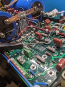
Alright, all fixed. B+ and B- rail fuses no longer wired with supply to their shells as PL factory wired it. Supply now goes to the fuse holder tips. The back planes are now wired to the fuse holder shell.
Also got the two B- wires for the Cylon meters properly installed off the B- shells.
The first photo is how PL wired it, second photo shows the rewire.
Also got the two B- wires for the Cylon meters properly installed off the B- shells.
The first photo is how PL wired it, second photo shows the rewire.
Attachments

That works George. I usually spin the tips and put one length of long stripped wire through both tips. Makes it easier.Alright, all fixed. B+ and B- rail fuses no longer wired with supply to their shells as PL factory wired it. Supply now goes to the fuse holder tips. The back planes are now wired to the fuse holder shell.
Also got the two B- wires for the Cylon meters properly installed off the B- shells.
The first photo is how PL wired it, second photo shows the rewire.