- Joined
- Jan 14, 2011
- Messages
- 75,905
- Location
- Gillette, Wyo.
- Tagline
- Halfbiass...Electron Herder and Backass Woof
ENIG?

It is also too damn expensive, everyone is scrambling for gold alternatives...Now we know what ENIG is
Making slow progress between dog walks and helping son fix his car.
I had the Phoenix connecters from another project, too late in the day to cut them to size, will have to wait til next weekend.
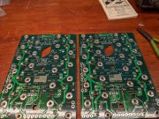
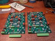
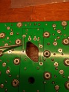
The 700 backplanes each take 2 jumper bus wires, something I don't remember the 400s having. Guess it's because of where the thermo breakers are mounted, right in the middle of the boards. The 400s use one, not two, and it's mounted between the two boards.
Hate to leave that flux on the boards for a week, but it'll have to wait.
Lee, what's the specific reason for the jumpers?There's a reason there are 2 jumpers on the 700 BP boards...
Nobody pushes the limits here Lee...There was some discussion about how hard some of us push these amps...Joe decided to go with two jumpers!!

Damn, silver plated bus wire to replace traces?
Looking at it now. The bus wire reinforces that massive plane that's interrupted by the thermo switch cutout. I dropped the wire into the backside for illustration. Cool!
Yep, Joe thought the traces were adequate in normal usage.....but......not all of us are "normal"....LOL!!