- Joined
- Jan 14, 2011
- Messages
- 75,921
- Location
- Gillette, Wyo.
- Tagline
- Halfbiass...Electron Herder and Backass Woof
Amen Joe!!

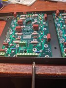
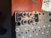
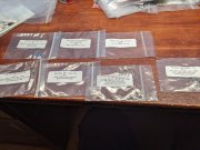
I just made sure the legs were straight and unbent.Now it's time to adjust the output transistor emitter and base leads to fit the solder cups. Later, the output transistors will be attached to a magnet on a stick and dropped down between the heatsink fins. Those leads need to have the correct spacing to enter those tiny solder cups.
Once all 24 outputs are checked for lead alignment they'll be put away until the "bring up" procedure. Output lead alignment can also be checked at anytime using one of the old sockets.
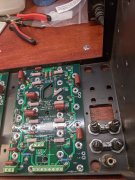
Some of those outputs were off enough that it would be a struggle. None were bent, just off enough to be a issue. These seem to all have rather blunt tips, seems like the earlier ones were more pointed.I just made sure the legs were straight and unbent.
Every one dropped in easily.
They still have them in most of the stores I frequent, tips are pre-bent now too. I still have two of them and use them too much probably...When I was a kid the only soldering equipment I had ever seen were those old Weller guns. I can remember seeing guys fixing cars and old radios with point to point wiring with them. Every hardware store had them along with those funky tips that need to be bent just right.
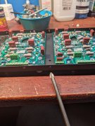
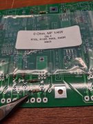
But they never really are...By god...0 ohms SHALL BE 0 ohms!!
")
Your right(of course!), 0.2 ohms on the Fluke. Guess you needed a small amount of resistance there as they replace a trace. Looking at how you use them on the double sided board confuses me. I'll look at the schematic this evening.But they never really are...