PL 700 Pro Build

George S.

Veteran and General Yakker
Joined
Feb 18, 2020
Messages
5,062
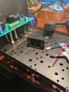
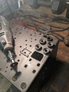
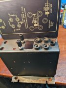
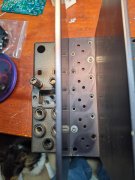
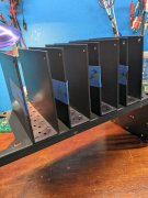
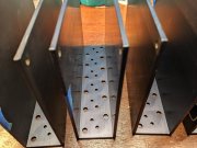
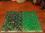
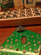
Starting mock up. I want to use a 20 amp IEC socket and cord. It should just fit in the accessory fan socket area. It's going to be tight but doable. This will be a full WOPL including Joe's awesome meters, using the original heavy steel chassis. All parts are at hand.
The part # for the socket is "Interpower 83030410". Most important is the solder tabs readily accept the 14 AWG wire. The cord was used for Dell 1000 watt desktop computer power supplies, and should be available new from Mouser or Digikey.
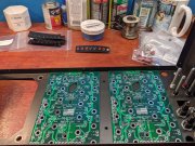
This is going to be a long, slow build, but I'll try to document it for the new guys.
 

Attachments

  • PXL_20211114_204414330.jpg
    PXL_20211114_204414330.jpg
    3.5 MB · Views: 77
Checking clearance and alignment of the chassis to the back plane boards. Looks good. This chassis was bent like so many of the commercial units are. I straightened it on the work bench with a makeshift press and wooden blocks.
This is one of the last 700s made, has the Jensen sticker on the heat sink, and I was concerned the dies were worn out by then or workmanship was lacking. Not the case, all the holes are punched correctly and none are offset on the chassis edge like I've seen in a photo.
Looks surprisingly good for a commercial unit.
 

Attachments

  • PXL_20211115_013428138.jpg
    PXL_20211115_013428138.jpg
    3.6 MB · Views: 73
Drilling out the IEC socket hole with the old Rockwell Delta. Long ago I would have just used a hand drill. Little easier and faster this way. Listening to The Allman Bros on the garage system.
 

Attachments

  • PXL_20211115_140542949.jpg
    PXL_20211115_140542949.jpg
    3.2 MB · Views: 67
Then I use a Dremel with a cutting disc. In the old days I'd just break the excess out with pliers. That's how we used to install gauges in the steel dashes of cars like air cooled VWs or Chevys. No one had hole saws back then or ever seen one. Hand files will finish the job.
 

Attachments

  • PXL_20211115_142438892.jpg
    PXL_20211115_142438892.jpg
    3.4 MB · Views: 45
Jim, you are so right!
Got the IEC socket installed, very tight, but fits well after a little massaging. The right most heat sink is bolted in, and I can just slip a piece of paper between the socket and heat sink.
That heatsink is held in and indexed with Joe's stepped nylon washers and assembly bolts which replace the original output transistor sockets and screws. These are tighter tolerance than the original output transistor sockets and screws. Due to the tighter tolerance, the bottom two holes between the chassis and heat sink are slightly off and won't take the step washer.
Next step is to drill IEC socket retaining holes sized for pop rivets. Then, mock up the heatsinks on the chassis for best alignment with the nylon step washers, number their positions and orientation for future assembly, and carefully ream out any misaligned holes.
Joe's instructions detail how to do this with drill bits, but I use a small tapered reamer, and do it now, not later.
 

Attachments

  • PXL_20211115_165348119.jpg
    PXL_20211115_165348119.jpg
    3.3 MB · Views: 59
  • PXL_20211115_162330491.jpg
    PXL_20211115_162330491.jpg
    3.6 MB · Views: 62
  • PXL_20211115_162446580.jpg
    PXL_20211115_162446580.jpg
    3.4 MB · Views: 57
Both of the 400s I WOPL'ed had same issue this 700 had, far bottom right output transistor screw holes were slightly misaligned. Easily fixed with drill or reamer. All other holes are aligned with a full complement of the nylon step washers installed. Note it's easy to install these heatsinks upside down. Best to do a mock up and check for these issues while the chassis is bare.
Now going to tear this all down and add two screws to strengthen the chassis.
 

Attachments

  • PXL_20211115_184844307.jpg
    PXL_20211115_184844307.jpg
    3.1 MB · Views: 34
The commercial amps suffered from rough treatment and many have bent chassis beside the transformer. If PL had added 2 more screws, some of this could have been minimized. I added two more screws, one top, one bottom, right where the chassis bends. This locks in the top and bottom plate significantly strengthening this area.
 

Attachments

  • PXL_20211115_200221731.jpg
    PXL_20211115_200221731.jpg
    3.4 MB · Views: 53
Alright, back at it. One important step is making sure there are no burrs or ridges on the heat sink holes that would puncture the silpads. I use a strip of wet and dry 1000 grit sandpaper that's finger width. Appx 9 holes on the 4 heatsinks had ridges, and there were about 3 burrs. Just get the high points, the anodizing is actually a good electrical insulator.
Cleaning with alcohol then preps the surface for good heat transfer.
 

Attachments

  • PXL_20211122_010844572.jpg
    PXL_20211122_010844572.jpg
    2.9 MB · Views: 24
Last edited:
The hardest soldering is on the backplanes. Joe recommends the solder in the photo. You will need a professional quality soldering station and the correct tip to install the solder cups and especially the PEM nuts. I use a old Hakko 936 with a chisel tip. Don't think a pointy tip will work on the PEM nuts. With the correct tools the solder cups and PEM nuts are easy.
There are lots of photos of builds with poor soldering of these nuts. I tend to go extreme on this step and aim for a nice donut on the back of the board, with a nice sloping meniscus or filet on the front.
 

Attachments

  • PXL_20211122_014159204.jpg
    PXL_20211122_014159204.jpg
    3.4 MB · Views: 55
  • PXL_20211122_012742062.jpg
    PXL_20211122_012742062.jpg
    3.4 MB · Views: 54
A small countersink tool is the best for taking the burrs off of holes.

A good machinist cleans both sides of every hole (unless the drawing says otherwise).
 
It takes a lot of solder to install those solder cups and PEM nuts. Consequently there is a lot of flux around those components and splattered across the boards. My wife gets me 99% isopropyl from Amazon, and 70% locally for cleaning the boards. I use a old tooth brush and a soft brass brush used by mechanics for cleaning the grease from their nails.
I use the 99% to get the worst of the flux off, then the 70% as a board wash.
All the PEM nuts get a 6-32 NC tap run through them now and a little synthetic grease. Tightening the transistors while watching the silpads just start to wrinkle requires clean properly lubed threads.
 
A small countersink tool is the best for taking the burrs off of holes.

A good machinist cleans both sides of every hole (unless the drawing says otherwise).
Doesn't work well here. Raises a small ridge around the outside of hole. Grinding with a ball stone has been discussed in the past as a better alternative, but, wet and dry sand paper under a finger tip cuts it flat very fast right on the bench.
Most all of these amps were built with mica insulators and heat sink compound, so they really weren't concerned about these issues. We're going to use thin silicone insulating pads "silpads" and that surface just needs a little touchup.
 
It shouldn’t raise a ridge. Something is not right then. Too much speed, pressure or both. On aluminum you just spin the tool by hand. Less flutes is better too. I learned that the hard way…

It is what any machinist would use, unless directed otherwise.
 
I hear you. Consider the two fins on either side of the hole and those holes were probably punched not drilled. They really don't look perfectly round. Not going to be easy for most people to machine these or even turn a countersink by hand.
I tried countersinking the first 400 I built. Got a very minor raised ridge. Decided it's best just to smooth it with fine cut wet and dry and move on.
 
  • Like
Reactions: J!m
Now it's time to adjust the output transistor emitter and base leads to fit the solder cups. Later, the output transistors will be attached to a magnet on a stick and dropped down between the heatsink fins. Those leads need to have the correct spacing to enter those tiny solder cups.
Once all 24 outputs are checked for lead alignment they'll be put away until the "bring up" procedure. Output lead alignment can also be checked at anytime using one of the old sockets.
 

Attachments

  • PXL_20211122_024821102.jpg
    PXL_20211122_024821102.jpg
    2.7 MB · Views: 33
Maybe a third of the outputs needed a very small tweak. Tomorrow I'll start populating the backplanes if I have time. Joe's circuit boards and components are of such high quality that they are a joy to work with. Only better boards I've ever seen are the gold plated HP boards in my scope. Later!
 
Maybe a third of the outputs needed a very small tweak. Tomorrow I'll start populating the backplanes if I have time. Joe's circuit boards and components are of such high quality that they are a joy to work with. Only better boards I've ever seen are the gold plated HP boards in my scope. Later!

ENIG is an industry nightmare George, not really done anymore. Too many reliability horror stories.
 
Back
Top