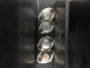
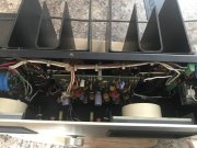
PL-400 DCP and WO light board

500 hz eh... 3 volts seems like a lot Joe. Not saying you didn't see that 2.99, I just don't recall input being that high to get 350....I'll pay closer attention when I test the next one..
it is actually half the RMS reading. The p-p is accurate, now updated in the RMS cells
 
Last edited:
What am I missing here? If P to P is 4.2 then RMS would be 4.2 X .707 = 2.9??
 
What am I missing here? If P to P is 4.2 then RMS would be 4.2 X .707 = 2.9??

Hi Lee
The RMS = Vp/SQRT(2)

The Vp-p is 2x Vp

Both are cited in the table as Vp-p is easier to set up if you are using a scope. The RMS is easier to set up if you are using your DMM.
 
How about bias?
Had my well pump for the house go up in smoke yesterday so have been a bit busy replacing that. Today I’ll pull her apart and lift the driver board so I can access the outputs easier then check bias. I was thinking about this and do I have to check a B+\B- transistor each channel? Their bias’ then add up (or cancel I suppose) which leaves you with your DC offset for that channel right? I really have to print a schematic as it’s a pain to see on my phone. And I need more coffee...
 
DC Offset is measured across the speaker terminals. Totally separate measurement from bias...
 
DC Offset is measured across the speaker terminals. Totally separate measurement from bias...
Yep, I realize that but bias affects it no? As in, if your +rail transistors are biased on 500mv and the negative rails are biased on 400mv, dc offset would be 100mv+? Sorry if that’s a silly question, you’re dealing with an electron herding n00b...
 
No..
Offset is not created that way. It's the net effective difference in gain between q1,q2.
 
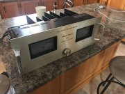
This quiffy PL4000 pre amp just dinked Linda... decided to go full blast as soon as it powered on. Shut it off quick, changed the rail fuses and powered back up with no input signal. Smoked another fuse... not good.
 

Attachments

  • 068CF96E-F469-4564-BDF2-0B941161F7C3.jpeg
    068CF96E-F469-4564-BDF2-0B941161F7C3.jpeg
    1.5 MB · Views: 4
Hmmm can’t find my stash of fuses... so how should I proceed to diagnose this? Power up on a 60w bulb then install one rail fuse at a time? Only the left fuse blew hard. Not sure if it’s the + or - without taking her top down.
 
If the fuse blew hard you've probably shorted an output. Fuse em again and do the DBT..
 
If the fuse blew hard you've probably shorted an output. Fuse em again and do the DBT..
Roger. Might be tomorrow, girlfriend cleaned the house up today after the mess I made with stereo gear, so I cooked supper then proceeded to eat far too much... pretty lazy rn...
 
Once again Linda’s on the kitchen table. I’ll look into her today I guess. I can’t find my box of fuses and I’m having trouble sourcing AGC or AGX locally, on a Sunday... otherwise I’d put the PL700 into service (without the pre amp which caused my problem of course), but I robbed two 5a fuses as I thought Linda just popped hers due to the volume spike, didn’t realize she was hurt worse than that :(
 

Attachments

  • 25D22CA8-6B74-4AB5-B190-52BBC7844ED0.jpeg
    25D22CA8-6B74-4AB5-B190-52BBC7844ED0.jpeg
    2.3 MB · Views: 3
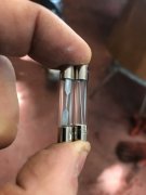
Here ls what I was able to source locally for fuses. AGC 4amp and 5amp. The 4 amp is the wire filament rated 125v. The 5 has no other markings but looks more like a slo-blow... they came from a gas station so intended for automotive. Yea or neigh?
 

Attachments

  • B15BE28A-D6F2-4D34-8422-7B4FC8375BA5.jpeg
    B15BE28A-D6F2-4D34-8422-7B4FC8375BA5.jpeg
    931.7 KB · Views: 3
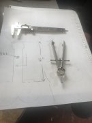
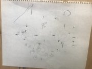
So my friend makes home made speaker lubricant... asked for some help with manual drafting. I’m not sure what to tell him.
 

Attachments

  • C5675762-72F6-4E21-83DF-BDE2C9C322FC.jpeg
    C5675762-72F6-4E21-83DF-BDE2C9C322FC.jpeg
    829 KB · Views: 7
Here ls what I was able to source locally for fuses. AGC 4amp and 5amp. The 4 amp is the wire filament rated 125v. The 5 has no other markings but looks more like a slo-blow... they came from a gas station so intended for automotive. Yea or neigh?
Use the 4A on the right Andrew. Looks like that is the 125VAC rated one.
 
Use the 4A on the right Andrew. Looks like that is the 125VAC rated one.
Will do soon as I’m finished at the “indoor shooting range”. I’m top left. Thank Joe
 

Attachments

  • 5288C308-B747-48D0-8856-EFD43056E74C.jpeg
    5288C308-B747-48D0-8856-EFD43056E74C.jpeg
    1.9 MB · Views: 8
  • Like
Reactions: J!m
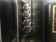
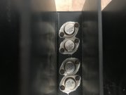
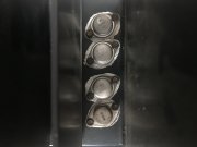
Looks like the left channel outputs have been changed they’re the NEC transistors. The right side are the PL909. The NEC’s show no shorts c-e the 909’s ALL seem to be shorted.
 

Attachments

  • 0CBB41D2-B74F-4D75-9963-9868DD38ABE4.jpeg
    0CBB41D2-B74F-4D75-9963-9868DD38ABE4.jpeg
    2.1 MB · Views: 4
  • 9ECD73BD-06CE-473B-BE94-FE56810F058C.jpeg
    9ECD73BD-06CE-473B-BE94-FE56810F058C.jpeg
    2 MB · Views: 4
  • 484A866A-6AD7-4C31-A92B-2620DEC48281.jpeg
    484A866A-6AD7-4C31-A92B-2620DEC48281.jpeg
    2.2 MB · Views: 4
  • 3950993E-EFA9-42E1-A7BE-F7018B7A874B.jpeg
    3950993E-EFA9-42E1-A7BE-F7018B7A874B.jpeg
    2.3 MB · Views: 4
  • B4F024C0-73DD-417C-9F95-D314BB19A6AA.jpeg
    B4F024C0-73DD-417C-9F95-D314BB19A6AA.jpeg
    2.2 MB · Views: 4
Back
Top