Looking very good Gene! One thing. How many nuts on the control board studs? Three? If so, one should be at the very bottom, then the long nylon standoff spacer, then the control board, then a nylon washer, then the securing nut. Should have a nylon on both sides of the control board mount hole, and some extra thread showing.

You are using an out of date browser. It may not display this or other websites correctly.
You should upgrade or use an alternative browser.
You should upgrade or use an alternative browser.
phase linear 400
- Thread starter gene french
- Start date
gene french
Veteran and General Yakker
- Joined
- Mar 6, 2022
- Messages
- 5,894
- Tagline
- music...the healer of souls...
there is one against the chassis...the nylon tube...another nut...a nylon washer the board...another nylon washer...a nut...and a few threads showing....that is what i thought you suggested....it is very sturdy and was not hard to tweak.....Looking very good Gene! One thing. How many nuts on the control board studs? Three? If so, one should be at the very bottom, then the long nylon standoff spacer, then the control board, then a nylon washer, then the securing nut. Should have a nylon on both sides of the control board mount hole, and some extra thread showing.
and thank you!!!
you saved me 3 times...
1. iec socket
2. insulating washers on inputs...
3. terminal strip...
i did not have to relocate the rectifier...its snug...but workable....the upgraded chassis is so much easier...
gene french
Veteran and General Yakker
- Joined
- Mar 6, 2022
- Messages
- 5,894
- Tagline
- music...the healer of souls...
and it adds a bit more room between the back planes and control board....there is one against the chassis...the nylon tube...another nut...a nylon washer the board...another nylon washer...a nut...and a few threads showing....that is what i thought you suggested....it is very sturdy and was not hard to tweak.....
and thank you!!!
you saved me 3 times...
1. iec socket
2. insulating washers on inputs...
3. terminal strip...
i did not have to relocate the rectifier...its snug...but workable....the upgraded chassis is so much easier...
Genemore progress...
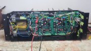
Nothing goes to the stud on the upper left channel backplane board except that ONE wire connecting the bus bar to the chassis.
Those orange wires need to be routed to the bus bar ground point, use the #10 solder lug that comes in the wire kit, that is what those are for Gene. Microvolts on those wires make a difference.
gene french
Veteran and General Yakker
- Joined
- Mar 6, 2022
- Messages
- 5,894
- Tagline
- music...the healer of souls...
yes sir...Gene
Nothing goes to the stud on the upper left channel backplane board except that ONE wire connecting the bus bar to the chassis.
Those orange wires need to be routed to the bus bar ground point, use the #10 solder lug that comes in the wire kit, that is what those are for Gene. Microvolts on those wires make a difference.
i can just solder it with the other grounds..right??
gene french
Veteran and General Yakker
- Joined
- Mar 6, 2022
- Messages
- 5,894
- Tagline
- music...the healer of souls...
oy its better under the cap screws....my bus bar has no place for a lug..yes sir...
i can just solder it with the other grounds..right??
which is better??
gene french
Veteran and General Yakker
- Joined
- Mar 6, 2022
- Messages
- 5,894
- Tagline
- music...the healer of souls...
that would be the bottom bus bar cap screw...so i am clear...oy its better under the cap screws....my bus bar has no place for a lug..
which is better??
gene french
Veteran and General Yakker
- Joined
- Mar 6, 2022
- Messages
- 5,894
- Tagline
- music...the healer of souls...
that would be the bottom bus bar cap screw...so i am clear...oy its better under the cap screws....my bus bar has no place for a lug..
which is better??
WOPL Sniffer
Veteran and General Yakker
yes sir...
i can just solder it with the other grounds..right??
Ya gotta quit being cheap and buy the BABB Gene. There are just too many ground wires for those scrawny copper strips.
Yes, you use one of the 4 - #10 solder lugs included in the wire kit under the negative cap ground screw...that would be the bottom bus bar cap screw...so i am clear...
gene french
Veteran and General Yakker
- Joined
- Mar 6, 2022
- Messages
- 5,894
- Tagline
- music...the healer of souls...
and then there was music!!!!
gene french
Veteran and General Yakker
- Joined
- Mar 6, 2022
- Messages
- 5,894
- Tagline
- music...the healer of souls...
gene french
Veteran and General Yakker
- Joined
- Mar 6, 2022
- Messages
- 5,894
- Tagline
- music...the healer of souls...
offset left .001
offset right .001
bias left .351
bias right .351
b+ 83.4
b- -83.4
+- 15v on control board...
listening to it play...
gene is happy
offset right .001
bias left .351
bias right .351
b+ 83.4
b- -83.4
+- 15v on control board...
listening to it play...
gene is happy
gene french
Veteran and General Yakker
- Joined
- Mar 6, 2022
- Messages
- 5,894
- Tagline
- music...the healer of souls...
gene french
Veteran and General Yakker
- Joined
- Mar 6, 2022
- Messages
- 5,894
- Tagline
- music...the healer of souls...
blind hog found an acorn....
thanks mr. joe
thanks mr. sniff
special thanks for my care package mr. george!!!
that was tough for me...
thanks mr. joe
thanks mr. sniff
special thanks for my care package mr. george!!!
and a case...lolYa gotta quit being cheap and buy the BABB Gene. There are just too many ground wires for those scrawny copper strips.
that was tough for me...
gene french
Veteran and General Yakker
- Joined
- Mar 6, 2022
- Messages
- 5,894
- Tagline
- music...the healer of souls...
and that is??Ya gotta quit being cheap and buy the BABB Gene. There are just too many ground wires for those scrawny copper strips.
Geneblind hog found an acorn....
thanks mr. joe
thanks mr. sniff
special thanks for my care package mr. george!!!
Not sure why you added a terminal block on the sidewall but 'oh well' The terminal block is only needed for dual voltage primary transformers...
Having this adds more loose AC wiring running around inside which is never a good thing (for an amp).
gene french
Veteran and General Yakker
- Joined
- Mar 6, 2022
- Messages
- 5,894
- Tagline
- music...the healer of souls...
thank you mr. joe....i appreciate your help and advice!!!Gene
Not sure why you added a terminal block on the sidewall but 'oh well' The terminal block is only needed for dual voltage primary transformers...
Having this adds more loose AC wiring running around inside which is never a good thing (for an amp).
gene french
Veteran and General Yakker
- Joined
- Mar 6, 2022
- Messages
- 5,894
- Tagline
- music...the healer of souls...
it was a suggestion to route the ac away from the b+voltage corner...Gene
Not sure why you added a terminal block on the sidewall but 'oh well' The terminal block is only needed for dual voltage primary transformers...
Having this adds more loose AC wiring running around inside which is never a good thing (for an amp).