- Joined
- Jan 14, 2011
- Messages
- 75,928
- Location
- Gillette, Wyo.
- Tagline
- Halfbiass...Electron Herder and Backass Woof
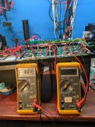
57 volts is what you get without your caps in line....
A good rule of thumb to figure rectified DC voltage from transformer secondaries is --Transformer secondary voltage X (timesa) 1.4 minus 1 volt for the diodes...---57 X 1.4=79.8- 1= 78.8....
A good rule of thumb to figure rectified DC voltage from transformer secondaries is --Transformer secondary voltage X (timesa) 1.4 minus 1 volt for the diodes...---57 X 1.4=79.8- 1= 78.8....