phase linear 400

laatsch55

Administrator,
Staff member
Joined
Jan 14, 2011
Messages
74,930
Location
Gillette, Wyo.
Tagline
Halfbiass...Electron Herder and Backass Woof
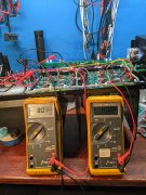
57 volts is what you get without your caps in line....

A good rule of thumb to figure rectified DC voltage from transformer secondaries is --Transformer secondary voltage X (timesa) 1.4 minus 1 volt for the diodes...---57 X 1.4=79.8- 1= 78.8....
 

George S.

Veteran and General Yakker
Joined
Feb 18, 2020
Messages
5,036
Gene, the aluminum plate came from Joe with the cap kit. He provides a short piece of threaded rod that threads into the cradle, and the plate drops onto that rod and is secured with a lock washer and nut, finger tight. Holds the caps securely.
The rectifier mounts on the same rod under the plate.
 
Last edited:

George S.

Veteran and General Yakker
Joined
Feb 18, 2020
Messages
5,036
57 volts is what you get without your caps in line....

A good rule of thumb to figure rectified DC voltage from transformer secondaries is --Transformer secondary voltage X (timesa) 1.4 minus 1 volt for the diodes...---57 X 1.4=79.8- 1= 78.8....
Lee, thank you!!!
 

gene french

Veteran and General Yakker
Joined
Mar 6, 2022
Messages
5,564
Location
guayabo de bagaces, guanacaste, costa rica....
Tagline
music...the healer of souls...
You can always run the same B+ and B- test on your other amp just to verify the test procedure. If you do, also see what VAC your getting off the secondaries.
The go back and carefully see what the problem transformer has for VAC on the secondaries.
Sounds like the rectifier is good.
i will compare to the 8 fin tomorrow!!!
 

Gepetto

Administrator
Staff member
Joined
May 15, 2011
Messages
14,049
Location
Sterling, MA
Tagline
Old 'Arn Enthusiast
all 4 legged diode test was fine in all positions....showed 4 one way conducting diodes
input ac was 123 volts...
i did not put in the new rectifier yet....
retested using existing rectifier...no change...plus and minus 57 volts....
i even plugged outside of the dbtester...no difference??
do you suggest tomorrow i test using the new rectifier???
57vrms AC rectifies to 80.5vDC
 

Gepetto

Administrator
Staff member
Joined
May 15, 2011
Messages
14,049
Location
Sterling, MA
Tagline
Old 'Arn Enthusiast
Gene, the aluminum plate came from Joe with the cap kit. He provides a short piece of threaded rod that threads into the cradle, and the plate drops onto that rod and is secured with a lock washer and nut, finger tight. Holds the caps securely.
The rectifier mounts on the same rod under the plate.
Gene will see on his next cap kit George...
 

Gepetto

Administrator
Staff member
Joined
May 15, 2011
Messages
14,049
Location
Sterling, MA
Tagline
Old 'Arn Enthusiast
yes sir, i certainly will!!!
mr. joe
all 3 sets of meters are tinted....
do you think the yellowish one would be illuminated better???
or am i better off with the clear one???
All the meters have a tint to them. Some early 4 fin units had a very dark tint to them and I believe you have one of those in the first unit you upgraded.

The meters you just pictured look like the bulk of PL meter, the pictures a page before look like the stock Jewell meters with the slightly tinted lenses. Those are what I have in all my amps and I run the warm white illumination.
 

gene french

Veteran and General Yakker
Joined
Mar 6, 2022
Messages
5,564
Location
guayabo de bagaces, guanacaste, costa rica....
Tagline
music...the healer of souls...
i just wrote to rob...and thanked him...his machines were exactly as he described....i did explain...there are many things i do not / did not understand...but you guys all pulled together to help me understand and learn...i want to thank joe again for hooking us up....i was treated fairly...i do appreciate....
life is good...and getting better each day!!!
will fire up the 8 fin tomorrow...and let her stew a while...joe should be shipping more stuff very soon...i am super excited!!!
 

Rob

New Around These Parts
Joined
Nov 26, 2020
Messages
49
My question about the outputs is, if I remember correctly, on both amps all the bottom transistors were all Toshiba's while the top 3 in each channel on both amps were PL transistors. Are these bottom transistors Pre-Drivers? I can see in the diagram that Q13 thru Q18 are PL909's and Q11 and Q12 are listed as 66546 transistors or SJ2741 noted in the diagram below.
 
Last edited:

Rob

New Around These Parts
Joined
Nov 26, 2020
Messages
49
Gene, From my understanding over the years when talking about outputs and lot #'s. When buying a set of outputs I would hope they are a matched set. But in the photo below the Toshiba has an R designation. you want to keep the same letters together because of the GAIN and other characteristics. Its just a better performance when doing that. If you put R's and O's together the amp will work but I like to keep that from happening.
View media item 32383
 
Top