phase linear 400

gene french

Veteran and General Yakker
Joined
Mar 6, 2022
Messages
5,564
Location
guayabo de bagaces, guanacaste, costa rica....
Tagline
music...the healer of souls...
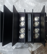
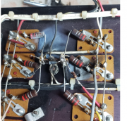
good morning....just opened up my two new to me pl400s....
have not tested anything....taking inventory in preparation for 2 out of 3 scenerio....
i noticed on the 8 fin...the outputs on one side are not matched....
please advise....i should probably check the bias and offset....
but, on the pl14 boards the offset adjustment is not necessary....as i read it...
i have only looked inside the 4 fin parts machine....mainy because top and bottom panels are missing....lol
anyway this should be interesting....
1655133335700.png
 

gene french

Veteran and General Yakker
Joined
Mar 6, 2022
Messages
5,564
Location
guayabo de bagaces, guanacaste, costa rica....
Tagline
music...the healer of souls...
well, for those who have never seen a tinted lens 8 fin 400.....pack your bags and come see mine....
i seem to have 3 sets of meters that are all tinted....lol
and i think i have diagnosed what was wrong with the 4 fin parts machine...lol
1655137046229.png

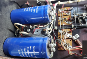
seems this same machine....has neither the cradle nor the clamps for the power supply caps....
they are simply siliconed in....
that saves money....lol
1655137173636.png
 

George S.

Veteran and General Yakker
Joined
Feb 18, 2020
Messages
5,036
Cool flash burn on that back wall. The storage caps have been replaced at some point and the original copper buss bar was pitched. Maybe Joe will repost that photo of his custom aluminum bus bar.
Are any of your tinted meters Dixson?
Since your tearing the 8 fin down it would be worthwhile to now test the transformer for B+ and -.
 

gene french

Veteran and General Yakker
Joined
Mar 6, 2022
Messages
5,564
Location
guayabo de bagaces, guanacaste, costa rica....
Tagline
music...the healer of souls...
Oops, Gene. I see your 4 fin has the flash burn. Well, you got lucky with a later transformer with a cradle. Cool.
here are the meters out of the 4 fin...
1655146695140.png

1655146726611.png

as you can imagine from looking at the back wall....only 2 of the remaining 909s tested good...and one has ever so slightly leakage in reverse...
3 of the 4 driver transistors tested good...

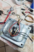
i have not tested the transformer or rectifier yet....mainly because i dont know how....
i am pretty sure the ac lines come into the rectifier from the transformer and the dc + and dc - is taken from the dc legs on the rectifier....
but, where does the negative lead from the dvm go???
gnd on the transformer???
if i am measuring for b+ and b-
1655147107665.png
 

gene french

Veteran and General Yakker
Joined
Mar 6, 2022
Messages
5,564
Location
guayabo de bagaces, guanacaste, costa rica....
Tagline
music...the healer of souls...
but, i am worried....the 8 fin does not have matching output transistors on one side....
and there are not enough good ones left from the 4 fin to populate the unmatched side...
how disasterous is it to have mismatched outputs....
i believe i read that a few of the transistors....those most closely matched will have the brunt of the load....
is that correct....??????
 

George S.

Veteran and General Yakker
Joined
Feb 18, 2020
Messages
5,036
Gene, if you want to test the transformer and rectifier, disconnect the B+ and B- leads from the storage caps. You could leave them connected if you so choose, but since this is a new to you antiquated old amp, I'd disconnect.
Meter gets set to VDC, ground lead connected to copper buss bar, positive to the B+ wire, then positive to the B- wire. Should be around +80 and -80 VDC if transformer, rectifier, and main fuse are good.
Your going to WOPL the 8 fin, right? Well your going to have plenty of old parts to build the 4 fin with.
 

gene french

Veteran and General Yakker
Joined
Mar 6, 2022
Messages
5,564
Location
guayabo de bagaces, guanacaste, costa rica....
Tagline
music...the healer of souls...
Gene, if you want to test the transformer and rectifier, disconnect the B+ and B- leads from the storage caps. You could leave them connected if you so choose, but since this is a new to you antiquated old amp, I'd disconnect.
Meter gets set to VDC, ground lead connected to copper buss bar, positive to the B+ wire, then positive to the B- wire. Should be around +80 and -80 VDC if transformer, rectifier, and main fuse are good.
Your going to WOPL the 8 fin, right? Well your going to have plenty of old parts to build the 4 fin with.
it is all taken apart....just a transformer with rectifier bolted to it...no caps ....they are in a box...lol
so connecting it the way you suggest will be mandatory....lol
and i do understand your instructions...even the fuse holders have been reclaimed....of course both rail fuses were blown...lol

well, george....there is nothing left of the 4 fin....seems the back of the pl 14 came in contact with the back plane....there are traces melted off of the pl14 board....someone put two new caps on the board but did not cut the leads...a lots of actual stuff melted....hope it happened near the 4th of july....because i am pretty sure there was a nice light show....maybe even poop stains on the carpet to boot....
the chassis is stripped and ready for whatever....right now it is stopping the door from slamming shut...

i have a new chassis ordered....more wire...light board....cap kit...dc protect board....
i bought the big rectifier in the original kit from joe...and it is snubbed and ready for installation....i will make an aluminum bracket to hold down the big caps....as the original 4 fin is wall mounted...both machines i had delivered today were either double face taped in place or a big glob of silicone to hold the big caps in place....i think its better to make a bracket...please send a pic of how you mounted your rectifier and the bracket that holds down your caps....did you put a cushion or something underneath ??? or are the caps just held against the cradle on the transformer....

so all i really need is working meters and a transformer....i am going to use the faceplate off of the 4 fin...it is the ugliest and really work on it...
i want an oak tree image between the meters with maybe 400 watts rms in some nice script across the bottom....or some words of wisdom printed on the face....i will rebrush the aluminium....i have my 4 fin that is my daily driver available for swapping parts too...the meters in that one have honeywell written on them...these 4 meters i have look alike with no writing...no clue what that means...i will have 4 machines to make a really nice wopl and 2 other working 400s....if i get lucky and plan this out....

all of my meters are tinted....i am disappointed in that...but, maybe the yellowish lights will look nicer than the clear....it has a not so attractive shadow from the needle....and the tint seems to dramatize that...i will have to listen to joe on that....he was betting the 8 fin was not tinted....well, its tinted...
lol

i still have your board that you donated to the cause for parts if necessary....i did reorder the transistors i robbed from it....
and now for your viewing pleasure....
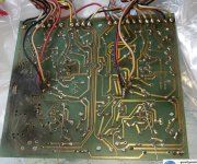
1655153409550.png
 

George S.

Veteran and General Yakker
Joined
Feb 18, 2020
Messages
5,036
Gene, there is a PDF document about the output transistors you should print out on Don's website. Go to Service Bulletins on the Watts Abundant side, look at "Output Transistors". I think this will help you. Also check out Don's link to the "Plastic Transistors".
Under Schematics, he has links to his PDFs hosted by Audio Karma. Lots of good info on those old amps and parts to be found there.
 

gene french

Veteran and General Yakker
Joined
Mar 6, 2022
Messages
5,564
Location
guayabo de bagaces, guanacaste, costa rica....
Tagline
music...the healer of souls...
Gene, there is a PDF document about the output transistors you should print out on Don's website. Go to Service Bulletins on the Watts Abundant side, look at "Output Transistors". I think this will help you. Also check out Don's link to the "Plastic Transistors".
Under Schematics, he has links to his PDFs hosted by Audio Karma. Lots of good info on those old amps and parts to be found there.
1655156776338.png

something else i noticed....i had a few that tested what i considered leaky....
seems i was wrong....or could be wrong....

1655156871595.png

however, i will chunk those that test shorted and or open....we know they are definitely bad...
thank you so much for pointing me in the right direction....
i will read more...but, this sure has made me feel better....and understand more....
thank you
 

George S.

Veteran and General Yakker
Joined
Feb 18, 2020
Messages
5,036
57 volts won't cut it. Be VERY careful with that transformer.
The rectifier has 4 diodes embedded in the potting compound. They are in-between those 4 lugs. Test the diodes like any others with your meter. If they check out, CAREFULLY mock up your transformer and rectifier and test again .
It's a center tap transformer with the center tap going to what should be the copper bus bar. The two transformer secondaries connect to the rectifier. This makes DC from the AC. This DC goes to the caps, one is B+ (80 VDC), the other is B-(-80 VDC.
Meter set to VDC, meter ground lead stays connected to the center tap( two wires on a S1) at the buss bar. Positive meter lead checks voltage of B+ and B- at the rectifier or wire still sobered on the rectifier. These are the wires that connect to the caps.
 

gene french

Veteran and General Yakker
Joined
Mar 6, 2022
Messages
5,564
Location
guayabo de bagaces, guanacaste, costa rica....
Tagline
music...the healer of souls...
57 volts won't cut it. Be VERY careful with that transformer.
The rectifier has 4 diodes embedded in the potting compound. They are in-between those 4 lugs. Test the diodes like any others with your meter. If they check out, CAREFULLY mock up your transformer and rectifier and test again .
It's a center tap transformer with the center tap going to what should be the copper bus bar. The two transformer secondaries connect to the rectifier. This makes DC from the AC. This DC goes to the caps, one is B+ (80 VDC), the other is B-(-80 VDC.
Meter set to VDC, meter ground lead stays connected to the center tap( two wires on a S1) at the buss bar. Positive meter lead checks voltage of B+ and B- at the rectifier or wire still sobered on the rectifier. These are the wires that connect to the caps.
understood....
 

gene french

Veteran and General Yakker
Joined
Mar 6, 2022
Messages
5,564
Location
guayabo de bagaces, guanacaste, costa rica....
Tagline
music...the healer of souls...
all 4 legged diode test was fine in all positions....showed 4 one way conducting diodes
input ac was 123 volts...
i did not put in the new rectifier yet....
retested using existing rectifier...no change...plus and minus 57 volts....
i even plugged outside of the dbtester...no difference??
do you suggest tomorrow i test using the new rectifier???
 

gene french

Veteran and General Yakker
Joined
Mar 6, 2022
Messages
5,564
Location
guayabo de bagaces, guanacaste, costa rica....
Tagline
music...the healer of souls...
Gene, there is a PDF document about the output transistors you should print out on Don's website. Go to Service Bulletins on the Watts Abundant side, look at "Output Transistors". I think this will help you. Also check out Don's link to the "Plastic Transistors".
Under Schematics, he has links to his PDFs hosted by Audio Karma. Lots of good info on those old amps and parts to be found there.
i thought they meant the lot numbers had to match as well....i see by the docs you noted....i was wrong...
as long as the make and number match per channel....got it...
i seem to be in pretty good shape at this point...
thanks sir...
 

George S.

Veteran and General Yakker
Joined
Feb 18, 2020
Messages
5,036
You can always run the same B+ and B- test on your other amp just to verify the test procedure. If you do, also see what VAC your getting off the secondaries.
The go back and carefully see what the problem transformer has for VAC on the secondaries.
Sounds like the rectifier is good.
 
Top