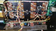
phase linear 400

two of marias kids....
the red shirt playing bass....abidan
the drummer playing drums...duh....isaac
zach is a graphics designer freelance and mixes music professionally....
abe is customer support for an on line casino....
good people...honest, hard working...

 
i am going over the board comparing to the trace map from the service manual....
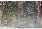
i just found a small break in a trace...it was not visible....but showed up with a continuity meter....
wow....i cant believe the little stuff that i have found....i will continue to check every avenue before i power back up....
i retouched every solder joint on the board....and am checking continuity on all....
thanks for hanging in there...
broken trace at the bottom....top is the broken solder joint...
1651786375583.png
 
ok...progress....
i disconnected the gray left and right outputs from the dcp board...
and powered up with the dbt...
a. both biases can now be easily set to 350mv left and right...using r8s
b. the left channel show -79v dc
c. the right output was 0v dc after setting the offset for that channel....
d. with the outputs not connected to the dcp board....i can hear the relay engage and disengage....
fuses ok...
no smoke...
no poop in the chair...

any observations....or am i now abandoned in the life raft waaaayyy out to sea...
lol....
thanks guys
 
.i started buying calves when they were 3 years from finishing high school.

Dang Gene, You buy livestock while they are still in school??? Excellent :)
 
  • Like
Reactions: J!m
ok...progress....
i disconnected the gray left and right outputs from the dcp board...
and powered up with the dbt...
a. both biases can now be easily set to 350mv left and right...using r8s
b. the left channel show -79v dc
c. the right output was 0v dc after setting the offset for that channel....
d. with the outputs not connected to the dcp board....i can hear the relay engage and disengage....
fuses ok...
no smoke...
no poop in the chair...

any observations....or am i now abandoned in the life raft waaaayyy out to sea...
lol....
thanks guys
It's time to pull out your oscilloscope, spectrum analyzer and TDR analyzer... :)

Are you handy with a schematic?
 
It's time to pull out your oscilloscope, spectrum analyzer and TDR analyzer... :)

Are you handy with a schematic?
It's time to pull out your oscilloscope, spectrum analyzer and TDR analyzer... :)

Are you handy with a schematic?

what a shame...i just put them in the shop for alignment...

now that would depend on your definition of handy...i know the difference between my elbow and a zener diode...lol
i will do my best...
 
Still have B- on the speaker terminal? From the terminal, follow it back and find the source. You can compare the good channel to the bad. Wow, consider this practice for building a WOPL.
 
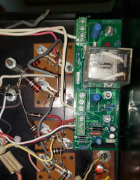
Gene, is the corner of the DCP IC blown out? Sure looks like it on this photo. Very bottom of the DCP board, hard to tell from photo, right beside R9.after transistor swap1.jpg
 
Gene, is the corner of the DCP IC blown out? Sure looks like it on this photo. Very bottom of the DCP board, hard to tell from photo, right beside R9.

no sir....as you can see, i removed the gray outputs from each channel going to j1 1 and j2 1 of dcp board...
i left the commons connected...both left and right bias were easily set at 350mv...
the left side has -79 volts (j1 1)...right side is working normally (j2 1)...and was easily able to set the offset for that channel...to 0...
with these lines removed the dcp board is functioning....you can hear/see the click on and the click off...

1651803200408.png

i am very close....but, as you can see...there is no physical damage to the dcp....
thank god and grandma!!!
 
Yes that was a pain in the ass! Bias would rise based on the tightness of the output screws on one row.


“IM HALF THE MAN I USED TO BE!!!”;)

you know....i was so wrapped up in my own little world.....i just realized your symbolism....
very good....thinking outside the box....
lol
really a good one....
 
Back
Top