phase linear 400

George S.

Veteran and General Yakker
Joined
Feb 18, 2020
Messages
5,036
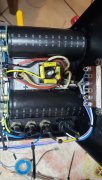
Bottom cap, bottom terminal, is B-, goes to B- fuse holder tip. Top cap, top terminal is B+, goes to B+ fuse holder tip. Observe correct polarity on those caps. And, if you have the wire, use correct color. Don't need heat shrink on fuse holder connections.
 

George S.

Veteran and General Yakker
Joined
Feb 18, 2020
Messages
5,036
The rectifier output goes to the B+ and B- terminals on the caps. Then a wire goes from each to the respective fuse holder tip. The backplane B+ and B- wires connect to the respective fuse holder base.
The B- cap terminal screw will have 2 wires, one from the rectifier, and one going to the B- fuse holder tip. Likewise B+.
This is shown clearly in my photos.
Keep asking any questions, no problem.
 

George S.

Veteran and General Yakker
Joined
Feb 18, 2020
Messages
5,036
My error Gene, there are FUSED and UNFUSED wires coming off the backplane. These need connected to the appropriate lug on the fuse holders.
Been awhile since I built these.
Fuse holder TIP remains UNFUSED, base is FUSED.
 

George S.

Veteran and General Yakker
Joined
Feb 18, 2020
Messages
5,036
Joe, has FUSED as going to shell(I've been calling it the "base", I'll try to do better). UNFUSED going to the tip. Yes.
Think of it this way. Power comes in the tip, passes through the fuse, and leaves through the shell connection. Therefore UNFUSED is the tip, and FUSED is the shell.
 

George S.

Veteran and General Yakker
Joined
Feb 18, 2020
Messages
5,036
Yup, no rush. Just be aware your going to have many wires to the B+ and B- fuse holders, so don't solder the tips or SHELL (see!) connections until you get everything laid, tied, and stripped (yes, amp building can be sexy).
Get that other backplane installed with two screws, build up your wire bundles knowing where they get soldered on the fuse holders or star ground. Get them laid, tied, stripped, then solder.
 

George S.

Veteran and General Yakker
Joined
Feb 18, 2020
Messages
5,036
Gene, do this strategically for easy soldering.
1. Gather all the wires going to that middle fuse holder shell. Get those soldered.
2. Then do that far right shell.
3. Then the middle tip.
4. Then the far right tip.
There's a lot of wiring that goes to those fuse holders, leave extra length and bend it and sculpt it to fit nicely.
Get some rest. Later.
 

Gepetto

Administrator
Staff member
Joined
May 15, 2011
Messages
14,067
Location
Sterling, MA
Tagline
Old 'Arn Enthusiast
please check...
i think is ok ...
will double / triple recheck tomorrow...
i am very appreciative...
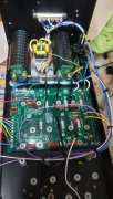
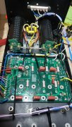
What you have done looks wired correctly, however...

  • You only wired in the left channel backplane, and wiring in the right channel will add more wires to the fuseholders. It looks like you have this all heatshrunk up and that will have to be undone to wire in the right channel.
  • You don't seem to be using the backplane hold down hardware that was supplied for the purpose of holding down the backplanes. You should do that so you don't accidentally have one of those shoulder washers pop out beneath the backplane.
  • You switched up the wire colors. Green designates B+ and blue designates B-. You used yellow for the B+ wiring from the cap to the fuseholders and black for the B- wiring from the cap to the fuseholders. Electrically it wont matter but it makes it harder to trace what is going on when you have different colors for the same node.
 

gene french

Veteran and General Yakker
Joined
Mar 6, 2022
Messages
5,581
Location
guayabo de bagaces, guanacaste, costa rica....
Tagline
music...the healer of souls...
i will change the colors tomorrow...
only the a/c heatshrink is shrunk...
the other is sitting there...
i put a drop of clear silicone under the plastic shoulder washers...as not to have them pop out ..
yes, i uses one washer and nut to hold it down...it is not there as i was cleaning under...before i shot the picture....
can you ship me 3 bias transistors tomorrow ...
please...
thank you for checking on me...
 
Top