phase linear 400

Gepetto

Administrator
Staff member
Joined
May 15, 2011
Messages
14,067
Location
Sterling, MA
Tagline
Old 'Arn Enthusiast
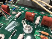
Mine are low also , I stop and looked at them thinking these are to low than I did find a lot of pic's of boards w them mounted like I did (But Lower than they should be. (any other components that also should be mounted higher?)

So Joe this would be hard to troubleshoot, I'm guessing it cause unwanted Noise if not install correctly (not installed) Should be able to buzz them out to the next component?
What did the customer say was wrong?
just conformally coated caps, the molded ones are fine. The control on how far the epoxy coating goes down the leads is not all that precise.

Occasional popping noise in the affected channel.
 

gene french

Veteran and General Yakker
Joined
Mar 6, 2022
Messages
5,581
Location
guayabo de bagaces, guanacaste, costa rica....
Tagline
music...the healer of souls...
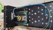
Gene, there are issues with your placement of the AC runs. If you leave it like this it's going to be noisy.
1. Line comes off the IEC and goes to main fuse TIP.
2. Line then comes off main fuse BASE and runs across the TOP of chassis to right above the thermal breaker. Then directly DOWN to the breaker.
3. Line then runs from breaker directly UP to chassis TOP, and back across the top, bending under the main fuse, to the chassis side wall, under the storage cap, down the chassis side wall, up over the cradle hugging it, to the transformer primary lead.
4. Neutral at the IEC goes beside the line under the storage cap, beside the wall, over and hugging the cradle to the other transformer primary wire.
5. See if a terminal strip was included with the chassis. If not, use one of the ones I sent. Make your Line and Neutral connections to the transformer primaries at the terminal strip leaving a empty space on the strip between Line and Neutral.
6. That chassis is extra deep, so you'll be able to move the plate away from the wall to pass wiring to the strip without the surgery on that plate I had to do to mine.
7. Lots of photos in my 400 S1 upgrade thread.
8. Use good wire.
 

Attachments

George S.

Veteran and General Yakker
Joined
Feb 18, 2020
Messages
5,036
Gene, looking MUCH better. Way to go!!! We're not going to let you fail or build a crappy amp!
The IEC ground lug is not used.
Per Joe, there will be one ground and only one ground, this is the star ground, the copper strap between the caps. There is a short ground wire from this strap to a chassis stud, clearly visible in many photos.
 

George S.

Veteran and General Yakker
Joined
Feb 18, 2020
Messages
5,036
thank you....
which documentation do i use for wiring up the back planes??
please
B-, B+, and ground backplane wires are certain colors. Make sure you have these correct, double check, triple check.
B+ wires go to the BASE of the B+ fuse holder, B- to the base of the B- fuse holder, and ground wires to the star ground.
The B+ and B- fuse holder TIPS get the B+ and B- wires from the storage cap terminals.
Laying these wires down neat, straight, and parallel with correct length will be a factor in build quality.
 

gene french

Veteran and General Yakker
Joined
Mar 6, 2022
Messages
5,581
Location
guayabo de bagaces, guanacaste, costa rica....
Tagline
music...the healer of souls...
The big one...page 37-38
thats what i was lookin for...
thanks....
page 37 thru 49

btw....
left board...
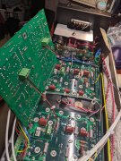
i checked those caps you said were suspedct....one did not check....
i removed the solder, scraped the bottom pigtails...resoldered
all of them....
they check now...
right board next
but probably tomorrow...
thank you
 

gene french

Veteran and General Yakker
Joined
Mar 6, 2022
Messages
5,581
Location
guayabo de bagaces, guanacaste, costa rica....
Tagline
music...the healer of souls...
B-, B+, and ground backplane wires are certain colors. Make sure you have these correct, double check, triple check.
B+ wires go to the BASE of the B+ fuse holder, B- to the base of the B- fuse holder, and ground wires to the star ground.
The B+ and B- fuse holder TIPS get the B+ and B- wires from the storage cap terminals.
Laying these wires down neat, straight, and parallel with correct length will be a factor in build quality.
understood....i found the chart ....
dont change the channel....
we will be back ....

thank you george...
i will have pics
 

gene french

Veteran and General Yakker
Joined
Mar 6, 2022
Messages
5,581
Location
guayabo de bagaces, guanacaste, costa rica....
Tagline
music...the healer of souls...
thats what i was lookin for...
thanks....
page 37 thru 49

btw....
left board...
i checked those caps you said were suspedct....one did not check....
i removed the solder, scraped the bottom pigtails...resoldered
all of them....
they check now...
right board next
but probably tomorrow...
thank you
37, 38, 39, 40....sorry
 

gene french

Veteran and General Yakker
Joined
Mar 6, 2022
Messages
5,581
Location
guayabo de bagaces, guanacaste, costa rica....
Tagline
music...the healer of souls...
Gene, looking MUCH better. Way to go!!! We're not going to let you fail or build a crappy amp!
The IEC ground lug is not used.
Per Joe, there will be one ground and only one ground, this is the star ground, the copper strap between the caps. There is a short ground wire from this strap to a chassis stud, clearly visible in many photos.
what is the ground lug in the middle of the left backplane top hole????
 

gene french

Veteran and General Yakker
Joined
Mar 6, 2022
Messages
5,581
Location
guayabo de bagaces, guanacaste, costa rica....
Tagline
music...the healer of souls...
HUH???
That is your one and only connection point from the single point ground (big copper bus bar between the 2 bulk caps) and chassis ground. View attachment 67239
understood....
i can make it up....but not mount permanantly until i get the bias transistors....
 
Top