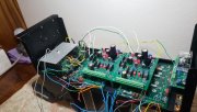
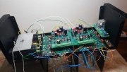
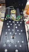
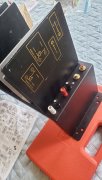
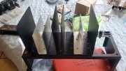
You can absolutely have the old anodize stripped and have it RE-anodzedNot to hijack this thought, but the D500 I picked up a few months ago is fully disassembled and getting bits and pieces done before I start reassembly sometime later this year. The rear section and heat sink is a heavy hunk of anodized aluminum but God only knows what horrors this poor system endured to get this beat up on the bottom edges. I am planning to dress this mess with filing and maybe some emery cloth so at least there won't be mashed and sharp edges exposed.
As I understand, there is no option to "re-anodize" the exposed aluminum areas, and painting is probably not the best option. Is there anything other than a REALLY BIG sharpie to use for touching up this mess?
You are using an out of date browser. It may not display this or other websites correctly.
You should upgrade or use an alternative browser.
You should upgrade or use an alternative browser.
phase linear 400
- Thread starter gene french
- Start date
gene french
Veteran and General Yakker
- Joined
- Mar 6, 2022
- Messages
- 5,884
- Tagline
- music...the healer of souls...
good morning....
well, got started this morning....
only to find out i forgot to reorder the bias transistors that i cut short....
i will write joe and ask to ship monday with a couple of new p straps...
anything else anyone can think of???
well, got started this morning....
only to find out i forgot to reorder the bias transistors that i cut short....
i will write joe and ask to ship monday with a couple of new p straps...
anything else anyone can think of???
No, but you can still get the most tedious and detailed part of the build done until you receive them, ie. all the wiring. Easy enough to pull the upper and lower assembly aid screws out of each backplane, lean them forward, install the bias transistors, reinstall the assembly aid screws, and start the bring up procedure. Really no big reason to wait.
Where is Mr. Mark Comer these days? I hope he is doing OK.
If you are out there Mark, stop by and say hi...
If you are out there Mark, stop by and say hi...
J!m
Veteran and General Yakker
I think he was dealing with family stuff… last I knew anyway.
gene french
Veteran and General Yakker
- Joined
- Mar 6, 2022
- Messages
- 5,884
- Tagline
- music...the healer of souls...
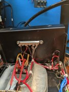
Gene, there are issues with your placement of the AC runs. If you leave it like this it's going to be noisy.
1. Line comes off the IEC and goes to main fuse TIP.
2. Line then comes off main fuse BASE and runs across the TOP of chassis to right above the thermal breaker. Then directly DOWN to the breaker.
3. Line then runs from breaker directly UP to chassis TOP, and back across the top, bending under the main fuse, to the chassis side wall, under the storage cap, down the chassis side wall, up over the cradle hugging it, to the transformer primary lead.
4. Neutral at the IEC goes beside the line under the storage cap, beside the wall, over and hugging the cradle to the other transformer primary wire.
5. See if a terminal strip was included with the chassis. If not, use one of the ones I sent. Make your Line and Neutral connections to the transformer primaries at the terminal strip leaving a empty space on the strip between Line and Neutral.
6. That chassis is extra deep, so you'll be able to move the plate away from the wall to pass wiring to the strip without the surgery on that plate I had to do to mine.
7. Lots of photos in my 400 S1 upgrade thread.
8. Use good wire.
Attachments
Geneprogress....
What is that orange wire on Backplane PAD 5L and 5R?
HI Geneprogress....
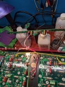
The mica caps on the control board are spaced really damn close to the board. The recommendation is that these be spaced off the board because the epoxy conformal coating often runs down the leads and can go through the feed through hole. Check these leads carefully to see that the lead is actually soldered on the bottom side of the board. I have debugged more than one for a customer that looked like it was soldered but in reality, there was what looked like a meniscus soldered to the lead but it was actually separated by a very thin coating of the epoxy conformal coating. You may be fine, but check.
Zoom in on page 9 of the recommended assembly order document to see what I am referring to. You will see the mica caps spaced off the board so that the bare lead is showing above the topside of the PCB
Attachments
gene french
Veteran and General Yakker
- Joined
- Mar 6, 2022
- Messages
- 5,884
- Tagline
- music...the healer of souls...
Gene, there are issues with your placement of the AC runs. If you leave it like this it's going to be noisy.
1. Line comes off the IEC and goes to main fuse TIP.
2. Line then comes off main fuse BASE and runs across the TOP of chassis to right above the thermal breaker. Then directly DOWN to the breaker.
3. Line then runs from breaker directly UP to chassis TOP, and back across the top, bending under the main fuse, to the chassis side wall, under the storage cap, down the chassis side wall, up over the cradle hugging it, to the transformer primary lead.
4. Neutral at the IEC goes beside the line under the storage cap, beside the wall, over and hugging the cradle to the other transformer primary wire.
5. See if a terminal strip was included with the chassis. If not, use one of the ones I sent. Make your Line and Neutral connections to the transformer primaries at the terminal strip leaving a empty space on the strip between Line and Neutral.
6. That chassis is extra deep, so you'll be able to move the plate away from the wall to pass wiring to the strip without the surgery on that plate I had to do to mine.
7. Lots of photos in my 400 S1 upgrade thread.
8. Use good wire.
i took the 8 fin off line and opened it up...and copied the wiring...thought that would be a good idea...i guess not ...
i will check all of this ...
gene french
Veteran and General Yakker
- Joined
- Mar 6, 2022
- Messages
- 5,884
- Tagline
- music...the healer of souls...
HI Gene
The mica caps on the control board are spaced really damn close to the board. The recommendation is that these be spaced off the board because the epoxy conformal coating often runs down the leads and can go through the feed through hole. Check these leads carefully to see that the lead is actually soldered on the bottom side of the board. I have debugged more than one for a customer that looked like it was soldered but in reality, there was what looked like a meniscus soldered to the lead but it was actually separated by a very thin coating of the epoxy conformal coating. You may be fine, but check.
Zoom in on page 9 of the recommended assembly order document to see what I am referring to. You will see the mica caps spaced off the board so that the bare lead is showing above the topside of the PCB
yes sir...i will check...
thank you
gene french
Veteran and General Yakker
- Joined
- Mar 6, 2022
- Messages
- 5,884
- Tagline
- music...the healer of souls...
Gene
What is that orange wire on Backplane PAD 5L and 5R?
i will check...
thank you..
And, set the control board safely aside. You have much wiring to do before it needs mounted. Leave it out of all photos for now. We need to see the backplanes in future photos.
We'll help you get this done correctly.
No rush.
We'll help you get this done correctly.
No rush.
gene french
Veteran and General Yakker
- Joined
- Mar 6, 2022
- Messages
- 5,884
- Tagline
- music...the healer of souls...
yes sir...i just wanted to see what it would look like...
back planes are not bolted down either...waiting for the bias transistors...thats why the ground lug is not there...
back planes are not bolted down either...waiting for the bias transistors...thats why the ground lug is not there...
Would help if you inserted 2 assembly aid screws and washers top and bottom into each backplane to secure them in place. This will help facilitate neat wiring. Also, secure your control board wiring that's coming off the backplanes into neat bundles with a zip ties. This will help prevent broken strands since your not using Phoenix Contacts on the backplanes.
MusicSteve
Journeyman
I have some NTE192A and stock 2N3403 , 2N5088, BD139The PL400RevE Backplane boards have the closer set of holes labeled NTE192, the outer set of holes labeled 5088
The PL700RevD Backplane boards (not released yet) have the closer set of holes labeled NTE192, the outer set of holes labeled 5088
From time to time, I get inquiries to send folks Pstraps because they are missing from their amp and they need them for the backplane builds. Since they cannot harvest them from the donors that they are converting, I have kept a small stash of Pstraps for those occasions. My stash is down to near zero.
I looked for small signal transistors which come equipped with Pstraps and the only readily available sources are the NTE192 and NTE192a (not pin compatible with the NTE192). I settled on designing in the NTE192 as the most available.
Using the NTE192 requires a 3/8" long standoff v. the standard 1/4" standoff we have been using in order to enable the flipover.
I have a lifetime supply of 2N5088s that I have collected over time, buying up all the available ONSemi stock that I have been able to find. The intention is to continue using those as they are low noise transistors. The NTE will prove to be acceptable in that application and will serve as my future bail out for those random Pstrap requests.
Gene, make sure you follow the standard procedure and do not be distracted by my bad influence.
so the 2N5088 is the best for less noise and longer wires w the Original backplane?
Yes the 2N5088 is used for its low noise figure and its high gainI have some NTE192A and stock 2N3403 , 2N5088, BD139
so the 2N5088 is the best for less noise and longer wires w the Original backplane?
MusicSteve
Journeyman
ThanksYes the 2N5088 is used for its low noise figure and its high gain
I have a bunch of them but I might order more since their so cheap Now
(I always like to have a lot stock)
I installed 2- of them last night and w shorter leads like you said.
seem to run better.
so since were taking about sharpie marker, I'm marking all the P-strap w the 2n5088 installed.
Update - The capacitor droop seems to be normal when running at high Volume levers, I hooked up another Quad 400II and it can drop into the high 60's vdc and sounded good and peak above 5-amp AC.
MusicSteve
Journeyman
Mine are low also , I stop and looked at them thinking these are to low than I did find a lot of pic's of boards w them mounted like I did (But Lower than they should be. (any other components that also should be mounted higher?)yes sir...i will check...
thank you
So Joe this would be hard to troubleshoot, I'm guessing it cause unwanted Noise if not install correctly (not installed) Should be able to buzz them out to the next component?
What did the customer say was wrong?

