Yes, found the solution after searching the globe.Is that the problem when we had our conversation about the heatshrink?

You are using an out of date browser. It may not display this or other websites correctly.
You should upgrade or use an alternative browser.
You should upgrade or use an alternative browser.
Newly assemble pl14 rev G bias trimmers do not work correctly
- Thread starter CrazyIvan
- Start date
- Joined
- Jan 14, 2011
- Messages
- 75,813
- Location
- Gillette, Wyo.
- Tagline
- Halfbiass...Electron Herder and Backass Woof
Don't doubt it. I searched my shit and never found anything close....I hope i told ya that...
- Joined
- Jan 14, 2011
- Messages
- 75,813
- Location
- Gillette, Wyo.
- Tagline
- Halfbiass...Electron Herder and Backass Woof
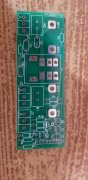
Sorry to sound dumb, are the rail fuses the screw in fuses on the back? I never removed those. The amp was working after the DC and cap install. Does the copper bus bar between the large caps connect the caps + on bottom cap to - on top cap? I replaced the new ones the same direction the old ones came out. I did cut off the other white wire and remove from PAD5R. See pics, still -.019 on the test points. No trimmer adjustment.View attachment 66517View attachment 66518View attachment 66519View attachment 66520
Yep, PS caps are in right. Yes, rail fuses are the screw in type on the back.
MusicSteve
Journeyman
your wiring not right , This is a Full-comp ????? I just did one and All my wires are hooked up for both boards Your PNP is not wied and is wired to the wrong spot & needs to be wired to the correct spot , you have no power for you Rt Control board 11,12
I would not hook up power yet, I will find mine wiring notes and post them
I would not hook up power yet, I will find mine wiring notes and post them
- Joined
- Jan 14, 2011
- Messages
- 75,813
- Location
- Gillette, Wyo.
- Tagline
- Halfbiass...Electron Herder and Backass Woof
The board is populated following the full comp directions. Thanks
Soooo...the output stage is full comp also...don't get insulted bud, just makin sure...whatcha got for outputs?
You did Lee...Don't doubt it. I searched my shit and never found anything close....I hope i told ya that...
WOPL Sniffer
Veteran and General Yakker
Ivan, who built the DCP??? It looks like C7 is in backwards
I am not insulted, I am new to this. I didnt know which way to build the board, full or quasi, I chose full. Im not sure how to answer what the output stage is.Soooo...the output stage is full comp also...don't get insulted bud, just makin sure...whatcha got for outputs?
- Joined
- Jan 14, 2011
- Messages
- 75,813
- Location
- Gillette, Wyo.
- Tagline
- Halfbiass...Electron Herder and Backass Woof
Take a pic of the outputs and post it...from the outside of the back...
I populated every thing on the PL 14 board to the full comp directions, should I have gone quasi? The transistors on the back panel are untouched and originalIvan, who built the DCP??? It looks like C7 is in backwards
- Joined
- Jan 14, 2011
- Messages
- 75,813
- Location
- Gillette, Wyo.
- Tagline
- Halfbiass...Electron Herder and Backass Woof
If the amp is in quasi configuration .....Houston, we have a problem. post a pic of the outputs, so we can tell if ity's a full or quasi, I'm betting quasi...
C7 on the DCP board looks like it's in backwards as Perry has noted. A close up pic of that would be nice... too
C7 on the DCP board looks like it's in backwards as Perry has noted. A close up pic of that would be nice... too
WOPL Sniffer
Veteran and General Yakker
Ivan, the DCP is the board from WattsAbundant for speaker protection. Who built it? Check C7 for backwardness insertedness
Skratch
Chief Journeyman
You have to build the board quasicomp the way your back wall is stock
- Joined
- Jan 14, 2011
- Messages
- 75,813
- Location
- Gillette, Wyo.
- Tagline
- Halfbiass...Electron Herder and Backass Woof
Ivan, you have a early 400 that was built with a quasi complementary point to point wired back wall, then the output transistors where selected and installed specifically for that quasi complementary back wall.
If you've not modified the back wall by rebuilding it full comp and installed the different output transistor configuration, then you need to build the control board quasi complementary to match it.
Also check your fuses for correct type and value. Some of these amps have had automotive fuses from the old Pontiac behind the barn or straight pieces of heavy copper wire.
Ask any question and we'll try to help. Nice job on the board!
Take a pic of the outputs and post it...from the outside of the back...


I bought it pre built from wattsIvan, the DCP is the board from WattsAbundant for speaker protection. Who built it? Check C7 for backwardness insertedness
- Joined
- Jan 14, 2011
- Messages
- 75,813
- Location
- Gillette, Wyo.
- Tagline
- Halfbiass...Electron Herder and Backass Woof
Your output stage is quasi-comp....
Oh No, I'll go back and rebuild it.You have to build the board quasicomp the way your back wall is stock