New WOPL 700 B Build

dtafil

Journeyman
Joined
Jan 23, 2020
Messages
101
#21
Hi Guys... ok, ran into a bit of an issue.

Brought up amp on variac/dim bulb tester with control board, level connections from faceplate pots, etc. Passed dim bulb, relays clicked.

Followed the PL12_20 bring up shortcuts, DMM hooked up across both rear RCA connectors, initially left channel connections, then right channel. Seeing around 1-2 mV per channel. So far, seemed fine.

Then went to the bias procedure... positive DMM lead to control board's upper left test point, negative lead to left speaker rear (white) output post. DMM reading ~2 mV, no turning of the left bias pot changed the reading. Moved over to the right channel, positive DMM lead to control board's right test point, negative lead to rear right (red) output post. This one immediately read ~42 mV, and turning the right bias pot on the control board resulted in mV changes, bit nothing close to the 0.350-0.380 range.

Maybe I'm following the wrong bias procedure with a full WOPL build (?)

Just for kicks, I powered down, turned the level pots all way down, and hooked up some cr@ppy test speakers, and an iPhone (volume waaaay down) and brought the amp back up. Relays still engaging, hit play, turned up the level pots perhaps a quarter turn each, and the iphone volume about halfway... got some Rush playing a bit distorted out of the right speaker, and barely anything at all out of the left. Just wanted to see if there was any sound whatsover. Hopefully that helps debug...

Initial pictures attached... hopefully someone can spot something or point me in the right direction. First full WOPL build, be gentle, trying to learn from the masters, lol.

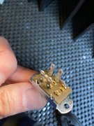
Original pic of the input jacks/coupling switch in stock form:
IMG_5139.jpeg

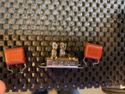
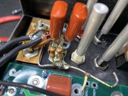
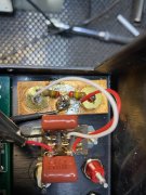
Modified to remove ground/bus bar, move resistors, added 1uF 250v film caps (probably can clean up that switch a bit on top):
IMG_5145.jpeg

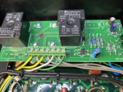
DC protect board... zobel network resistors and caps removed:
IMG_5195.jpeg

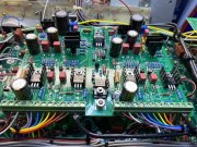
Shot of the control board with phoenix wiring following the wiring guide:
IMG_5194.jpeg

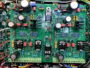
And overhead shot, in case there's something amiss there:
IMG_5196.jpeg

Finally, the backplane boards, prior to wiring in (a bit messy, wasn't planning on posting that one); jumpers (JMP1-4) and fuses were added after this pic, tape removed from bias transistor p clamps as well :)
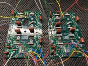
IMG_5101.jpeg

Thanks for any suggestions! Happy to grab any more pics if needed...
 
Last edited:

dtafil

Journeyman
Joined
Jan 23, 2020
Messages
101
#22
I did go back and tore that coupling switch out after looking at the pic above. It can't be this easy, but just in case, sharing for others...

Thought I was being smart by using those smaller-sized film caps across the left/right switch tabs... however, mounted them using the bottom holes in each tab, whose leg(s) may have inadvertently contacted the switch cover metal/pointed tabs which appear to standing almost straight up. In any event, probably not my root cause, but you never know. Coupling switch looks better now, taking a break. Pics:

IMG_5199.jpeg

IMG_5201.jpeg

is there a better way perhaps to go clean up the RCA input jack area? Get rid of that copper piece perhaps?
 

dtafil

Journeyman
Joined
Jan 23, 2020
Messages
101
#26
Have you got the rail fuses in?
Aha! I may owe you one!!! Found all four 5-amp AGX fuses blown... rebuilding my switch, reinstalling 4 new 5 amp AGX fuses, fingers crossed.

Going back a few days, there was a time when I was flipping the amp over after installing the first row of transistors where I suspect a wire from the backplane, destined for the control board, shorted on something. Caught it immediately with the variac/dim bulb, powered off, and doublechecked the taped up wires. Nothing on the backplane boards looked bad, small fuses are intact, so I carried on. That's what took out the fuses I'm guessing (?)

Should I try next time with only the left or right rail fuses inserted perhaps?
 
Last edited:

laatsch55

Administrator,
Staff member
Joined
Jan 14, 2011
Messages
74,244
Location
Gillette, Wyo.
Tagline
Halfbiass...Electron Herder and Backass Woof
#27
If things are right fuses should be OK to leave in. Check the fuses on the backplanes too, if you took out some rail fuses, you may have taken them out..
 

Gepetto

Administrator
Staff member
Joined
May 15, 2011
Messages
13,553
Location
Sterling, MA
Tagline
Old 'Arn Enthusiast
#29
You installed the 4 5x20mm fuses in the backplanes correct Dave? None of your pictures show them installed.
 

dtafil

Journeyman
Joined
Jan 23, 2020
Messages
101
#30
You installed the 4 5x20mm fuses in the backplanes correct Dave? None of your pictures show them installed.
Hi Joe - Yes, added those and the jumpers after the photos... thanks for checking though! I'm about to get that switch reinstalled and we shall see...
 

Gepetto

Administrator
Staff member
Joined
May 15, 2011
Messages
13,553
Location
Sterling, MA
Tagline
Old 'Arn Enthusiast
#31
If it's OK to leave these alone, that's fine too this time around...
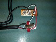
If your OCD kicks in again Dave, it is easier to solder to the copper plate if you drill 3 small holes in the plate and install the 2 resistors and wire for the shield ground while the plate is uninstalled, then trim all leads flush to the plate and proceed with reassembly. Like pictured below. You need more heat than was applied in your current picture to neaten it up. Then clean all the flux off with flux remover before install. PL700B 002.JPG
 

dtafil

Journeyman
Joined
Jan 23, 2020
Messages
101
#32
Thanks Joe. I got it looking much better :)

So, one step forward, maybe a step back. Popped in the four new 5 amp fuses, brought up slowly on the variac, dim bulb test failed. Should I start pulling and testing outputs transistors? I'm guessing this happened either right after the first or second row of outputs was installed and brought up. All the fuses are fine... confirmed on both backplanes as well.
 

Gepetto

Administrator
Staff member
Joined
May 15, 2011
Messages
13,553
Location
Sterling, MA
Tagline
Old 'Arn Enthusiast
#33
For initial bring up Dave you should have only the bottom row of output devices in. Then add as you achieve success. You only need the bottom row to make the amp act like an amp. The upper rows increase the power output capability, a row at a time.
 

dtafil

Journeyman
Joined
Jan 23, 2020
Messages
101
#34
For initial bring up Dave you should have only the bottom row of output devices in. Then add as you achieve success. You only need the bottom row to make the amp act like an amp. The upper rows increase the power output capability, a row at a time.
Yep. I'll go back to square one. I did do one row at a time from the bottom, always passed the dim bulb test. Maybe pop out the contol board as well, go back to just one row on the bottom (in terms of the outputs), test the first row of outputs prior to reinserting them?
 

Gepetto

Administrator
Staff member
Joined
May 15, 2011
Messages
13,553
Location
Sterling, MA
Tagline
Old 'Arn Enthusiast
#35
Did you ever have only the bottom row in and the control board in? That is a test you should run if you have not already. I sense that you did the row by row without the control board in and enabled. It makes it hard to debug where things might have gone wrong when everything is in.
 

dtafil

Journeyman
Joined
Jan 23, 2020
Messages
101
#36
You’re spot on. The control board wasn’t in... just went row by row for the backplanes. I’ll leave the control board in (the DC protect board as well which was added), pull the outputs, test/reinsert the bottom row, and report back. Thanks Joe.
 

dtafil

Journeyman
Joined
Jan 23, 2020
Messages
101
#37
OK, pulled and tested all the outputs... all tested good.

Populated the bottom row of the backplanes (4 outputs only) with control board and DC protect board installed... failed dim bulb test.

Removed control board, failed dim bulb.

Also, thinking back to the short a few days ago, almost positive the wire that may have shorted was one of the bias emitter leads that wasn't properly taped off. Maybe took out the left-side bias transistor? Pulled and tested that bias transistor... tested OK.

Pulled both backplances, and going to review all solder joints for proper shortness; I was pretty careful about that. Ordering up some additional wire from @NavLinear and going to rewire as well to pretty it all back up.

@Gepetto Does it make sense to replace both bias transistors anyway while I'm back in this deep?
 
Last edited:

Gepetto

Administrator
Staff member
Joined
May 15, 2011
Messages
13,553
Location
Sterling, MA
Tagline
Old 'Arn Enthusiast
#38
Only replace what is broken, if the bias transistors are good, leave them. If you pulled the control board and the problem persisted, then something happened between your earlier, successful backwall bring up without the control board and your present situation. Have you narrowed it further by pulling either the right channel or left channel rail fuses?

Debug is nearly always a quest to narrow down the scope of the problem. Pulling right channel fuses, check. Pulling left channel fuses, check.

You may narrow it down to one channel that way. Then on the failing channel you would pull only the B+ fuse, check. Then the B- fuse, check,

Follow the debug logic?? Too bad you pulled it all apart already.
 

dtafil

Journeyman
Joined
Jan 23, 2020
Messages
101
#39
Yep, followed the logic. Just wanted to get under those backplanes, more for an additional check of solder joints, checking for a potential short, etc. Although its a pain, this is actually very helpful for my first WOPL build, learning so much as I go thanks to you guys. I guess I simply enjoy this stuff, like a bunch of others on these boards.

BTW, any of the black faceplates in stock?
 

Gepetto

Administrator
Staff member
Joined
May 15, 2011
Messages
13,553
Location
Sterling, MA
Tagline
Old 'Arn Enthusiast
#40
Yep, followed the logic. Just wanted to get under those backplanes, more for an additional check of solder joints, checking for a potential short, etc. Although its a pain, this is actually very helpful for my first WOPL build, learning so much as I go thanks to you guys. I guess I simply enjoy this stuff, like a bunch of others on these boards.

BTW, any of the black faceplates in stock?
One left I believe...
 
Top