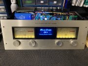
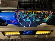
New WOPL 700 B Build

dtafil

Journeyman
Joined
Jan 23, 2020
Messages
101
#42
Some updates...

Long story short - redid all the wiring and busbar... much, much happier now. Trimmed up both backplanes just a bit more (nothing looked too tall), but my issue appeared to be overtightened sil-pads. Bout half of them are slightly torn or perforated. (Thought we were supposed to crank 'em down and back off a 1/4 turn; Lesson learned, ;) ). Also, the two 500 mA fused were indeed blown on the left backplane, but visually looked absolutely fine. Pulled 'em to test, and found they were both shot. New fuses installed.

Reinstalled the backplanes, bottom row of outputs only, floated the common ground. Getting roughly +100.6 vDC and -100.6 vDC on the the rails, and +98.5 vDC / -98.5 vDC on the left backplane using TP's 11 & 12; the right backplane is +99.0 vDC / -99.0 vDC. DC protect board is clicking for both relays, passing dim bulb test; I'm breathing again. Loved @markthefixer 's video with Gene Hackman... probably screamed "It's alive!!!" over here as well. It's been a good day.

Also, seeing about 50-60 mV on the speaker outputs w/ the 10K resistor in place... no control board hooked up yet. New sil-pads in the works...
 

Gepetto

Administrator
Staff member
Joined
May 15, 2011
Messages
13,553
Location
Sterling, MA
Tagline
Old 'Arn Enthusiast
#43
Some updates...

Long story short - redid all the wiring and busbar... much, much happier now. Trimmed up both backplanes just a bit more (nothing looked too tall), but my issue appeared to be overtightened sil-pads. Bout half of them are slightly torn or perforated. (Thought we were supposed to crank 'em down and back off a 1/4 turn; Lesson learned, ;) ). Also, the two 500 mA fused were indeed blown on the left backplane, but visually looked absolutely fine. Pulled 'em to test, and found they were both shot. New fuses installed.

Reinstalled the backplanes, bottom row of outputs only, floated the common ground. Getting roughly +100.6 vDC and -100.6 vDC on the the rails, and +98.5 vDC / -98.5 vDC on the left backplane using TP's 11 & 12; the right backplane is +99.0 vDC / -99.0 vDC. DC protect board is clicking for both relays, passing dim bulb test; I'm breathing again. Loved @markthefixer 's video with Gene Hackman... probably screamed "It's alive!!!" over here as well. It's been a good day.

Also, seeing about 50-60 mV on the speaker outputs w/ the 10K resistor in place... no control board hooked up yet. New sil-pads in the works...
5-6 in-lbs Dave. You weren’t listening to the jokers on the forum were you?
 

dtafil

Journeyman
Joined
Jan 23, 2020
Messages
101
#47
Updates to this point; so close :(

Got through the backplane power up (no control board attached) using new sil-pads and a little less torque on the output screws, lol. Passed the dim bulb test for every row of transistors, and took readings from both rails (-101.1/+101.1) with the same readings on TP11/12 respectively for both backplanes after every row installation. DC protect relay clicking every time, all looked fine.

Added in the control board (varica and dim bulb still attached)... was able to get left-hand bias set to .365 vDC, no issue. Right-hand bias would only adjust from ~54mV to 63mV, something not right. Powered down, checked fuses. Right hand positive (5A) fuse blown. Replaced with another 5A; brought back up, bias was working fine now... biased that side to .365 vDC as well. Removed variac & dim bulb, plugged in amp to power strip, turned on amp... small pop, 5A fuse blown again. Relays clicked, panel lights on etc.

Just tested the 15 and -15 test points on the control board... getting +15.07 vDC on the +15 test point, and -15.36 vDC on the -15 test point.

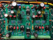
Didn't hit this until I added the control board back in... does anything look amiss? Happy to take other pics/measurements, just need some suggestions on any other test points on the control board (or elsewhere) to debug... thanks for any pointers!

IMG_5403.jpeg
 
Last edited:

Gepetto

Administrator
Staff member
Joined
May 15, 2011
Messages
13,553
Location
Sterling, MA
Tagline
Old 'Arn Enthusiast
#49
Hi Dave
Do you have any burrs around any of the heatsink holes on the right channel that are piercing through? It would be the third heatsink away from the transformer. I would be inclined to strip the 5 outputs above the driver in that heat sink stack and retry your experiment again. If it does not repeat with just the driver in then I would strip it all the way down and inspect for burrs and also for crushed nylon shoulder washer in one of the holes. The rapid DV/DT without the DBT and Variac may be bringing out a marginal arcing condition.
 

dtafil

Journeyman
Joined
Jan 23, 2020
Messages
101
#50
So, looking even better... before taking out the transistors and 3rd heatsink, checked on the transistor bolts... a couple of them seemed like another 1/4 to 1/2 turn easily, so gently torqued them all back down. New fuse, brought slowly back up on the variac/dim bulb, and all appears well :)

Letting it idle now, but was able to get both bias pots to .350 vDC, letting them sit there for a bit longer.

Any other sanity tests/checks Joe/anyone?

Am looking at Amazon right now for a 1/4", inch/pound torque wrench. I'm starting to see how important the proper torque is! Is there one you guys like, or miles will vary?
 

Gepetto

Administrator
Staff member
Joined
May 15, 2011
Messages
13,553
Location
Sterling, MA
Tagline
Old 'Arn Enthusiast
#52
So, looking even better... before taking out the transistors and 3rd heatsink, checked on the transistor bolts... a couple of them seemed like another 1/4 to 1/2 turn easily, so gently torqued them all back down. New fuse, brought slowly back up on the variac/dim bulb, and all appears well :)

Letting it idle now, but was able to get both bias pots to .350 vDC, letting them sit there for a bit longer.

Any other sanity tests/checks Joe/anyone?

Am looking at Amazon right now for a 1/4", inch/pound torque wrench. I'm starting to see how important the proper torque is! Is there one you guys like, or miles will vary?

Have you brought it up fast like the failure the last time Dave? Recalling that you had successfully brought it up on the variac but then when you turned it on quickly, it failed.
 

WOPL Sniffer

Veteran and General Yakker
Joined
Aug 10, 2015
Messages
11,228
Location
Minnie-Soda
Tagline
Screw it
#53
Even if you did have a inch Lb torque wrench, the setting is so low you could get a "False Click" because of tight fit etc..... Get your face down there and see if you have contact
 

WOPL Sniffer

Veteran and General Yakker
Joined
Aug 10, 2015
Messages
11,228
Location
Minnie-Soda
Tagline
Screw it
#54
if you reefed on all your silpad/transistors/fasteners... Shit can them and do it over.... CORRECTLY. if you compromised the sil pads, you probably bent and screwed up the transistor ears too, stressing all that shit.
 

dtafil

Journeyman
Joined
Jan 23, 2020
Messages
101
#57
Just had to torque those transistor bolts down a bit... “ just right”, lol

Onto the cosmetics for a bit.
 

dtafil

Journeyman
Joined
Jan 23, 2020
Messages
101
#60
Light board now installed... as much as I like the warm white, think I'm going to switch over to the blue LED board... and then get to work on the knobs. May snag some from a 4000 I have for now if I can't get these up to snuff...

I did notice the delamination (?) on the acrylic insert... one of you guys still sell the officially licensed WOPL ones? I did pick up a black faceplate from Joe; love to drop a new insert into that one. Can you shoot me a PM if you have one available?

Her's as it sits for now... any wiring suggestions, please let me know. Tried to follow along with some good threads you guys have out there.

I also noticed my right meter is a bit off at idle... will look into how to zero out.

IMG_5420.jpeg IMG_5421.jpeg
 
Last edited:
Top