dtafil
Journeyman
- Joined
- Jan 23, 2020
- Messages
- 101
Hi Guys... ok, ran into a bit of an issue.
Brought up amp on variac/dim bulb tester with control board, level connections from faceplate pots, etc. Passed dim bulb, relays clicked.
Followed the PL12_20 bring up shortcuts, DMM hooked up across both rear RCA connectors, initially left channel connections, then right channel. Seeing around 1-2 mV per channel. So far, seemed fine.
Then went to the bias procedure... positive DMM lead to control board's upper left test point, negative lead to left speaker rear (white) output post. DMM reading ~2 mV, no turning of the left bias pot changed the reading. Moved over to the right channel, positive DMM lead to control board's right test point, negative lead to rear right (red) output post. This one immediately read ~42 mV, and turning the right bias pot on the control board resulted in mV changes, bit nothing close to the 0.350-0.380 range.
Maybe I'm following the wrong bias procedure with a full WOPL build (?)
Just for kicks, I powered down, turned the level pots all way down, and hooked up some cr@ppy test speakers, and an iPhone (volume waaaay down) and brought the amp back up. Relays still engaging, hit play, turned up the level pots perhaps a quarter turn each, and the iphone volume about halfway... got some Rush playing a bit distorted out of the right speaker, and barely anything at all out of the left. Just wanted to see if there was any sound whatsover. Hopefully that helps debug...
Initial pictures attached... hopefully someone can spot something or point me in the right direction. First full WOPL build, be gentle, trying to learn from the masters, lol.
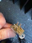
Original pic of the input jacks/coupling switch in stock form:
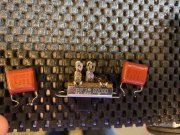
Modified to remove ground/bus bar, move resistors, added 1uF 250v film caps (probably can clean up that switch a bit on top):
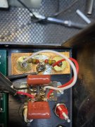
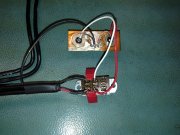
DC protect board... zobel network resistors and caps removed:
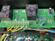
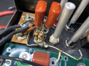
Shot of the control board with phoenix wiring following the wiring guide:
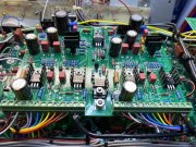
And overhead shot, in case there's something amiss there:
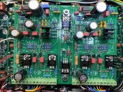
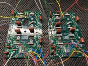
Finally, the backplane boards, prior to wiring in (a bit messy, wasn't planning on posting that one); jumpers (JMP1-4) and fuses were added after this pic, tape removed from bias transistor p clamps as well
Thanks for any suggestions! Happy to grab any more pics if needed...
Brought up amp on variac/dim bulb tester with control board, level connections from faceplate pots, etc. Passed dim bulb, relays clicked.
Followed the PL12_20 bring up shortcuts, DMM hooked up across both rear RCA connectors, initially left channel connections, then right channel. Seeing around 1-2 mV per channel. So far, seemed fine.
Then went to the bias procedure... positive DMM lead to control board's upper left test point, negative lead to left speaker rear (white) output post. DMM reading ~2 mV, no turning of the left bias pot changed the reading. Moved over to the right channel, positive DMM lead to control board's right test point, negative lead to rear right (red) output post. This one immediately read ~42 mV, and turning the right bias pot on the control board resulted in mV changes, bit nothing close to the 0.350-0.380 range.
Maybe I'm following the wrong bias procedure with a full WOPL build (?)
Just for kicks, I powered down, turned the level pots all way down, and hooked up some cr@ppy test speakers, and an iPhone (volume waaaay down) and brought the amp back up. Relays still engaging, hit play, turned up the level pots perhaps a quarter turn each, and the iphone volume about halfway... got some Rush playing a bit distorted out of the right speaker, and barely anything at all out of the left. Just wanted to see if there was any sound whatsover. Hopefully that helps debug...
Initial pictures attached... hopefully someone can spot something or point me in the right direction. First full WOPL build, be gentle, trying to learn from the masters, lol.
Original pic of the input jacks/coupling switch in stock form:

Modified to remove ground/bus bar, move resistors, added 1uF 250v film caps (probably can clean up that switch a bit on top):

DC protect board... zobel network resistors and caps removed:

Shot of the control board with phoenix wiring following the wiring guide:

And overhead shot, in case there's something amiss there:

Finally, the backplane boards, prior to wiring in (a bit messy, wasn't planning on posting that one); jumpers (JMP1-4) and fuses were added after this pic, tape removed from bias transistor p clamps as well

Thanks for any suggestions! Happy to grab any more pics if needed...
Last edited:

