Greg
Journeyman
- Joined
- Jun 11, 2022
- Messages
- 204
Ill press my soldering Iron to my tongue should help me understand what your saying lol ?NO NO NO!!! CUT THE RED WIRE!!! NOT THE BLUE!!!

Ill press my soldering Iron to my tongue should help me understand what your saying lol ?NO NO NO!!! CUT THE RED WIRE!!! NOT THE BLUE!!!
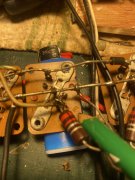
Pretty sure the PL transistor sockets are marked on the inside for base and emitter, collector is the case, identify whether those wires are base or emitter then follow the documents for joes board as to which pin they go too?So ended up here as best I could The 4 White wires w Red trace are attached to the left hand side bus ( Main Cap Side Bus ) Across each of the 4 transistor rows / banks ? My PRONOUNS are I DONT KNOW ...? I identify as Confused ....View attachment 74348
Yes I have done my best to review the documents and search out the Forums for another reference of similar nature but no luck .....Knowing that all 4 wires ( white / red trace ) are on left side ( Cap ) side of each of the Main Buss run for the MAIN transistors. I cannot make sense of it ? Is my First build so trying ..Pretty sure the PL transistor sockets are marked on the inside for base and emitter, collector is the case, identify whether those wires are base or emitter then follow the documents for joes board as to which pin they go too?
Hard to see in your pic but those look like collector bus wires. Never worked on a S2 though. Do the transistor screws go through where that bus is soldered too? Pretty sure those go to the bus bar between the caps but don’t take my word for it, I’m REAL good at letting smoke out!

Lol yes Just dont see a reason to clean the flux off old board if im install new WOPL but whats a few more Carcinogens in my system going to do at this point any way ....Spraying Flux off to near flash point in kitchen will report back Fire department on its way I hear sirens
Yes Exactly Left Side ( Main Cap Side ) Buss bar each row I admit Im not Experienced enough to properly identify a location in the WOPL DocumentsLooks like they are tied to the base bus bars for each column. Full comp amp right?...
YES ! Left side buss ( main cap side ) each row each of the four white wires / red trace are connected to each row as such I am not experinced enough to identify what to do I see no reference in the WOPL build docs that reference these wires that I know ofLooks like they are tied to the base bus bars for each column. Full comp amp right?...