NEW PL700 Series 2 WOPL BUILD

Greg

Journeyman
Joined
Jun 11, 2022
Messages
204
So ended up here as best I could The 4 White wires w Red trace are attached to the left hand side bus ( Main Cap Side Bus ) Across each of the 4 transistor rows / banks ? My PRONOUNS are I DONT KNOW ...? I identify as Confused .... Wires.jpg
 

AngrySailor

Veteran and General Yakker
Joined
Oct 15, 2014
Messages
3,419
Tagline
---not quite right
So ended up here as best I could The 4 White wires w Red trace are attached to the left hand side bus ( Main Cap Side Bus ) Across each of the 4 transistor rows / banks ? My PRONOUNS are I DONT KNOW ...? I identify as Confused .... View attachment 74348
Pretty sure the PL transistor sockets are marked on the inside for base and emitter, collector is the case, identify whether those wires are base or emitter then follow the documents for joes board as to which pin they go too?
 

Greg

Journeyman
Joined
Jun 11, 2022
Messages
204
Pretty sure the PL transistor sockets are marked on the inside for base and emitter, collector is the case, identify whether those wires are base or emitter then follow the documents for joes board as to which pin they go too?
Yes I have done my best to review the documents and search out the Forums for another reference of similar nature but no luck .....Knowing that all 4 wires ( white / red trace ) are on left side ( Cap ) side of each of the Main Buss run for the MAIN transistors. I cannot make sense of it ? Is my First build so trying ..
 

AngrySailor

Veteran and General Yakker
Joined
Oct 15, 2014
Messages
3,419
Tagline
---not quite right
Hard to see in your pic but those look like collector bus wires. Never worked on a S2 though. Do the transistor screws go through where that bus is soldered too? don’t take my word for it, I’m REAL good at letting smoke out!
 
Last edited:

Greg

Journeyman
Joined
Jun 11, 2022
Messages
204
Hard to see in your pic but those look like collector bus wires. Never worked on a S2 though. Do the transistor screws go through where that bus is soldered too? Pretty sure those go to the bus bar between the caps but don’t take my word for it, I’m REAL good at letting smoke out!
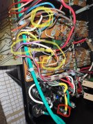
This is typical per channel regarding these White wires / red trace 2 each channel Left/ right......Just dont know where to land them at all Im not seeing a reference for them .....Maybe Im not looking hard enough lol Been 8 hours on this today just tryen to find out what the heck to do with them lol !!
WIRE @ PER CHANNEL TYP.jpg
 

WOPL Sniffer

Veteran and General Yakker
Joined
Aug 10, 2015
Messages
11,522
Location
Minnie-Soda
Tagline
Screw it
Lol yes Just dont see a reason to clean the flux off old board if im install new WOPL but whats a few more Carcinogens in my system going to do at this point any way ....Spraying Flux off to near flash point in kitchen will report back Fire department on its way I hear sirens

Sorry, I'm high on Alky-Seltzer Cold Plus.....
 

AngrySailor

Veteran and General Yakker
Joined
Oct 15, 2014
Messages
3,419
Tagline
---not quite right
I’m too full of beer and mom’s spaghetti to be much use. I’d identify where those wires go to on the back plane. There’s only three options, I’m pointing to the emitter. The other pin is base and the one with the tie bar which the screws go through are collector. Then refer to the documents.
 

Attachments

Greg

Journeyman
Joined
Jun 11, 2022
Messages
204
Looks like they are tied to the base bus bars for each column. Full comp amp right?...
Yes Exactly Left Side ( Main Cap Side ) Buss bar each row I admit Im not Experienced enough to properly identify a location in the WOPL Documents
 

Greg

Journeyman
Joined
Jun 11, 2022
Messages
204
Looks like they are tied to the base bus bars for each column. Full comp amp right?...
YES ! Left side buss ( main cap side ) each row each of the four white wires / red trace are connected to each row as such I am not experinced enough to identify what to do I see no reference in the WOPL build docs that reference these wires that I know of
 

Greg

Journeyman
Joined
Jun 11, 2022
Messages
204
I see no reference to these white ? red trace wires mentioned in the WOPL docs that I can recognize ? IMG_9064.jpg 3.jpeg
 

laatsch55

Administrator,
Staff member
Joined
Jan 14, 2011
Messages
74,912
Location
Gillette, Wyo.
Tagline
Halfbiass...Electron Herder and Backass Woof
Because those are not standard color code. Someone has changed them. Identify the source of the wires, then refer to documentation for that source.
 

laatsch55

Administrator,
Staff member
Joined
Jan 14, 2011
Messages
74,912
Location
Gillette, Wyo.
Tagline
Halfbiass...Electron Herder and Backass Woof
You are showing connection diagram for the PL36 board. You need to refer to the WO Pl-14-20 wiring diagram..
 

Gepetto

Administrator
Staff member
Joined
May 15, 2011
Messages
14,035
Location
Sterling, MA
Tagline
Old 'Arn Enthusiast
1 goes to RCA signal input
2 goes to RCA ground
3 goes to the negative fused B- rail (all the negative output collectors are attached to this Q108 to Q117C watch out, the PL schematic has errors)
4 goes to the negative side current limit resistor junction of R127 and Q110E (appears to be a yellow wire in your picture)
5 goes to bus bar ground between the 2 bulk caps
PNP goes to the base of Q108
6 goes to the output (junction of all the 0.33 ohm emitter resistors)
7 goes to the positive fused B+ rail (all the positive output collectors are attached to this Q107 to Q116C watch out, the PL schematic has errors)
8 goes to the positive side current limit resistor junction of R110 and Q109E
9 goes to the base of Q107
10 goes to the emitter of Q107
11 goes to unfused B+
12 goes to unfused B-

1677473154754.png
 
Top