J!m
Veteran and General Yakker
For what it's worth: there are muffin fans that run quieter AND move more air than their grandparents did.
I have an upgrade fan (quieter and more volume) for my Alesis HD24 recorder I'll probably never get installed... It was a suggested upgrade for anyone using these recorders as they run HOT.
I have an upgrade fan (quieter and more volume) for my Alesis HD24 recorder I'll probably never get installed... It was a suggested upgrade for anyone using these recorders as they run HOT.

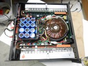
![DSCN3146[1].JPG](/data/attachments/77/77732-e688400d03f05dc14880a5cf72b61bac.jpg?hash=5ohADQPwXc)
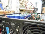
![DSCN3149[1].JPG](/data/attachments/77/77733-7d629a0154f5267ae09b83717777d7e8.jpg?hash=fWKaAVT1Jn)