Kenny Nelson's WOPL 400 conversion.

since it is one channel Lee, I would strip the outputs down to the RCA410 level and go from there.

Yep, that's what I thought too. Beins this employs Global Negative feedback, if this was contained on the board, I couldn't scope probe from Q1 to see where it started??
 
How did we get from blowing R2's to this? What'd I miss?
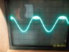
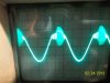
Nothing Jer. With R2's replaced and not loaded the amp would power up. Starting at a 10mv input signal and slowlygoing up I could get to where I could see the waveform and not blow R2 if I kept it where I began to see it and not go past that input level.
 
I'm assuming the cause of R2's blowing was found?? How'd we get from there to testing the output (with osc in one channel)?


Jer, I'm not sure of the sequence of events other than there was a shorting event on the backwall when Ken plugged it in. When it got here the only thing I found was R2 blown. Until I figured that out we had no waveform, after replacing R2's we had waveform for 2 seconds after energizing said amp. What I should have done in the first place was walk the input voltage up from almost nothing. I usually start at 125mv which is about 2-3 watts. things generally don't go boom there if it's not a power supply problem.
 
Hi Lee
one other thing to check is the health of the positive half germanium transistor (thinking it is the 1304). It could be clamping the positive going signal. The easiest way to disable is lift one end of the 1N4148 diode in series with the 1304 collector
 
The zoebel network is not stock to Don's board. It is a scavanged double 10 ohm 3 watt resistors that read 6.1 ohms and a brand new 250 volt .1uf polypro cap.. And they check good.
 
Hi Lee
one other thing to check is the health of the positive half germanium transistor (thinking it is the 1304). It could be clamping the positive going signal. The easiest way to disable is lift one end of the 1N4148 diode in series with the 1304 collector

10-4 Joe, checks good in circuit, but yeah, that don't tell ya shit sometimes. Will do Joe.
 
One leg of diode lifted, C11 replaced----at 23mv 2nd pic at 30mv
 

Attachments

  • 100_2385.jpg
    100_2385.jpg
    90.3 KB · Views: 24
  • 100_2386.jpg
    100_2386.jpg
    90.2 KB · Views: 20
Good sine wave with just the RCA-410 in. Going back with the 21194's one at a time.
 
As is mica?? As in collector to ground check?

Yes Lee, you are down to either an insulation breakdown or an output device that is wounded and cannot support the rail to rail voltage. Based on your waveform a hunch is that the breakdown is on the lower half of the bridge.
 
I had a waveform like that one and the tech I was working with said it was "ringing" as in oscillation at a certain frequency and amplitude, but only at the peak of the positive voltage. I think it turned out to be a transistor that was bad or installed backward. It was many years ago.

Mark
 
Back
Top