Inverted back plates build

laatsch55

Administrator,
Staff member
Joined
Jan 14, 2011
Messages
74,281
Location
Gillette, Wyo.
Tagline
Halfbiass...Electron Herder and Backass Woof
#42
It is Alive

The hardest part was putting in the drivers. I remembered something about magnets so I got out my little pocket magnet pencil It made things much easier but still was a fight
I found that checking the leg alinement in an old base helped a lot
I must have stewed up something with the little inserts as they stuck up from the board. Did I put them in from the wrong side?

View attachment 22489


The threaded 6-32 standoffs that are soldered in the backplanes??? If so, you are not the first to do that...how about a close up of the backplanes??
 

grapplesaw

Veteran and General Yakker
Joined
Aug 13, 2014
Messages
2,765
Location
Vancouver
Tagline
---
#43
The threaded 6-32 standoffs that are soldered in the backplanes??? If so, you are not the first to do that...how about a close up of the backplanes??
Here is a shot. The threaded standoff's were soldered from the bottom and the little inserts for the drivers were soldered from the top as in attached photo

image.jpg
 

grapplesaw

Veteran and General Yakker
Joined
Aug 13, 2014
Messages
2,765
Location
Vancouver
Tagline
---
#44
Here is the DC offset at outputs 3mv and .8 mv

Any fine tuning this ??

I will have to redo this one
I just noticed it was set on Ac volts

Well you got me after all Lee!!!

View attachment 22490
I retested with the meters set on DC volts and got unexpected results. Less than .1 MV in each channel. Does this look right seams to low.
I have left out of the input the high pass cap and resistor and wired direct from the RCA plug to the volume controls.

Comments any one????? image.jpg
 

laatsch55

Administrator,
Staff member
Joined
Jan 14, 2011
Messages
74,281
Location
Gillette, Wyo.
Tagline
Halfbiass...Electron Herder and Backass Woof
#45
DC offset using the Rev E board with the OPA op-amps are typically .000, to .001 VDC.....ZERO to 1 millivolt...
 

grapplesaw

Veteran and General Yakker
Joined
Aug 13, 2014
Messages
2,765
Location
Vancouver
Tagline
---
#48
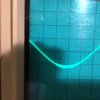
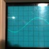
Help please. On load test I get wave distortion on bottom half and on both channels area identical. THD is very low and this was at about 1 volts output when this started. The more volts the greater the distortion
I Tried two different source supply for input so suspect something in the power supply bridge rectifier area

Any thoughts

Did I cook one of the small caps on the bridge rectifier???? I think that because it is equal distortion both channels and only one channel fuses installed at a time it has to be supply cap side or main control board. Could bias transistors cause any effect?? I will isolate the DCP board and check bridge rec with meter next I guess

Glen
image.jpg image.jpg image.jpg image.jpg
 
Last edited:

laatsch55

Administrator,
Staff member
Joined
Jan 14, 2011
Messages
74,281
Location
Gillette, Wyo.
Tagline
Halfbiass...Electron Herder and Backass Woof
#49
One channel fuses at a time?? You mean rail fuses?? Put all 4 in and try it again....
 

laatsch55

Administrator,
Staff member
Joined
Jan 14, 2011
Messages
74,281
Location
Gillette, Wyo.
Tagline
Halfbiass...Electron Herder and Backass Woof
#52
Glen, IIRC , there's something weird that happens when all rail fuses are not in and functioning....
 

grapplesaw

Veteran and General Yakker
Joined
Aug 13, 2014
Messages
2,765
Location
Vancouver
Tagline
---
#55
Glen, IIRC , there's something weird that happens when all rail fuses are not in and functioning....
I bypassed the DCP board
That eliminated that and any concern of the supply lines running between the DCP board and binding post

I all removed all other test leafs from unit
 

grapplesaw

Veteran and General Yakker
Joined
Aug 13, 2014
Messages
2,765
Location
Vancouver
Tagline
---
#57
Gets worse the lower the frequency......what power output??
50 mv input wide open volume control and wave Starr's to break up on bottom half of wave at1.7 volts output with 7 of ohm load

The voltage point has increased over time before distortion

Here is a pushed up voltage photo at 2500 hz

image.jpg
 
Last edited:
Top