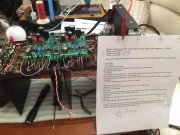
I'm Buying a "Mule" PL400

Gepetto

Administrator
Staff member
Joined
May 15, 2011
Messages
13,473
Location
Sterling, MA
Tagline
Old 'Arn Enthusiast
Hi Mark
After you get done doing the above measurement, this is something you should try.

Have the following wires attached to the control board. Detach and tape off the other signal wires.

12L=Attach
11L=Attach
10L=Detached and Taped
9L=Detach signal wire and attach one end of a 22 ohm 1/2W resistor
8L=Detached and Taped
7L=Attach
6L=Detach and tape signal wire. Connect other end of 22 ohm resistor attached to 9L above along with one end of a second 22 ohm 1/2W resistor to 6L
4L=Detach and tape signal wire. Connect other end of second 22 ohm resistor that was attached to 6L above.
3L=Detach and tape signal wire. Jumper to 12L above
10R=Detached and Taped
9R=Detach signal wire and attach one end of a 22 ohm 1/2W resistor
8R=Detached and Taped
7R=Attach
6R=Detach and tape signal wire. Connect other end of 22 ohm resistor attached to 9R above along with one end of a second 22 ohm 1/2W resistor to 6R
5R=Attach
4R=Detach and tape signal wire. Connect other end of second 22 ohm resistor that was attached to 6R above.
3R=Detach and tape signal wire. Jumper to 12R above
 

mlucitt

Veteran and General Yakker
Joined
Jun 24, 2011
Messages
3,339
Location
Jacksonville, FL
Q11 and Q12 should be conducting at the same time Mark. That is what makes bias in the amp. Q11 and Q12 work in Class A mode.

When you thought that R39 was smoking, were you measuring the voltage across it? Prior test results were showing that you had about 0.5V across it. If you still have ~0.5V across it then the wattage you are dissipating is 25 milliwatts. The 1/2W resistor you have in the R38 and R39 positions are 500mW resistors so you should never see any heat in them with only 25 mW being dissipated in them.
Joe,
With the only Q11L and Q12L installed, all wires connected (as in the above test) the DBT lamp was glowing and the Variac set at "60V", the voltage across R39L was -3.40VDC. This was the first chance I got to have a meter across the resistor during a test.

I am waiting on some 22 Ohm resistors to try the test you outlined for me. Kicking myself because I used to have at least 100 of every component on the Rev A Control Boards...
 

Gepetto

Administrator
Staff member
Joined
May 15, 2011
Messages
13,473
Location
Sterling, MA
Tagline
Old 'Arn Enthusiast
Joe,
With the only Q11L and Q12L installed, all wires connected (as in the above test) the DBT lamp was glowing and the Variac set at "60V", the voltage across R39L was -3.40VDC. This was the first chance I got to have a meter across the resistor during a test.

I am waiting on some 22 Ohm resistors to try the test you outlined for me. Kicking myself because I used to have at least 100 of every component on the Rev A Control Boards...
So now that you have this setup, short C-E of the Q6 bias transistor and re-measure the R38 and R39 voltages. Then with respect to the copper bus bar between the bulk caps AND the C-E still shorted, measure what you see at Pin9 and Pin4 of the control board.

And where does the wire attached to Pin5R connect to?
 

mlucitt

Veteran and General Yakker
Joined
Jun 24, 2011
Messages
3,339
Location
Jacksonville, FL
5R is the ground because the wire from the Star Ground was long enough. I thought about shortening it and moving it to 5L.

As soon as I hook up the 22 Ohm resistors, I'll take the measurements and report back to you.

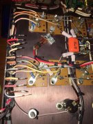
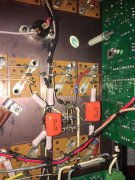
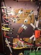
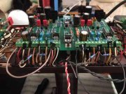
Some more chassis pictures, please let me know if you see something my eyes have missed.
Left Top.jpg
Left Bottom.jpg
Right Top.jpg
Right Bottom.jpg
 

Gepetto

Administrator
Staff member
Joined
May 15, 2011
Messages
13,473
Location
Sterling, MA
Tagline
Old 'Arn Enthusiast
5R is the ground because the wire from the Star Ground was long enough. I thought about shortening it and moving it to 5L.

As soon as I hook up the 22 Ohm resistors, I'll take the measurements and report back to you.

Some more chassis pictures, please let me know if you see something my eyes have missed.
View attachment 36182
View attachment 36183
View attachment 36184
View attachment 36185
Hi Mark
This test was with your prior setup where you measured 3.40V on R39.

Can you reconstruct that test setup for the above measurements?
 

mlucitt

Veteran and General Yakker
Joined
Jun 24, 2011
Messages
3,339
Location
Jacksonville, FL
Lately, I have tried to be as consistent as possible to avoid introducing additional variables.
Testing is done with only the driver transistors in place, none of the output transistors.
All wires to the Control Board are in place, the DBT is in use, and the Variac is turned up to 60V; at which point the 150W DBT gets fairly bright (I can no longer see just the orange filament).
The supply voltage stabilizes and I make the measurements quickly, then remove the power.
 

mlucitt

Veteran and General Yakker
Joined
Jun 24, 2011
Messages
3,339
Location
Jacksonville, FL
Hi Mark
After you get done doing the above measurement, this is something you should try.

Have the following wires attached to the control board. Detach and tape off the other signal wires.

12L=Attach
11L=Attach
10L=Detached and Taped
9L=Detach signal wire and attach one end of a 22 ohm 1/2W resistor
8L=Detached and Taped
7L=Attach
6L=Detach and tape signal wire. Connect other end of 22 ohm resistor attached to 9L above along with one end of a second 22 ohm 1/2W resistor to 6L
4L=Detach and tape signal wire. Connect other end of second 22 ohm resistor that was attached to 6L above.
3L=Detach and tape signal wire. Jumper to 12L above
10R=Detached and Taped
9R=Detach signal wire and attach one end of a 22 ohm 1/2W resistor
8R=Detached and Taped
7R=Attach
6R=Detach and tape signal wire. Connect other end of 22 ohm resistor attached to 9R above along with one end of a second 22 ohm 1/2W resistor to 6R
5R=Attach
4R=Detach and tape signal wire. Connect other end of second 22 ohm resistor that was attached to 6R above.
3R=Detach and tape signal wire. Jumper to 12R above
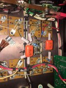
UPDATE

Joe, these are the results of the above test:
Conditions - Q6 Bias transistors bypassed. DBT and Variac connected and set to 60V. Drivers only.
Measurements before wires taped and jumpered:
R38L 2.4VDC.......R38R 2.2VDC
R39L 3.40VDC.....R39R 2.2VDC

Measurements after wires taped and jumpered:
R38L 0VDC.........R38R 0VDC
R39L 0VDC.........R39R 0VDC
These voltages were measured with the Variac at 60V and then at 120V because the DBT stayed dim, no change in voltage.

Control Board measurements, referenced to Star Ground with 120V supply.
Pin 9L +.001VDC.......Pin 9R +.002VDC
Pin 4L -.022VDC........Pin 4R -.022VDC

I left the wires taped and jumpered in case you want me to make additional measurements or make incremental changes.

Thanks for helping with this vexing issue. Some pictures:
Wires Taped and Jumpered.jpg
Test Complete.jpg
 
Last edited:

Gepetto

Administrator
Staff member
Joined
May 15, 2011
Messages
13,473
Location
Sterling, MA
Tagline
Old 'Arn Enthusiast
UPDATE

Joe, these are the results of the above test:
Conditions - Q6 Bias transistors bypassed. DBT and Variac connected and set to 60V. Drivers only.
Measurements before wires taped and jumpered:
R38L 2.4VDC.......R38R 2.2VDC
R39L 3.40VDC.....R39R 2.2VDC

Measurements after wires taped and jumpered:
R38L 0VDC.........R38R 0VDC
R39L 0VDC.........R39R 0VDC
These voltages were measured with the Variac at 60V and then at 120V because the DBT stayed dim, no change in voltage.

Control Board measurements, referenced to Star Ground with 120V supply.
Pin 9L +.001VDC.......Pin 9R +.002VDC
Pin 4L -.022VDC........Pin 4R -.022VDC

I left the wires taped and jumpered in case you want me to make additional measurements or make incremental changes.

Thanks for helping with this vexing issue.

Mark
Hi Mark
Still confusing so can you clear some things up.

Which wires were taped and jumpered???

"Measurements after wires taped and jumpered:
R38L 0VDC.........R38R 0VDC
R39L 0VDC.........R39R 0VDC
These voltages were measured with the Variac at 60V and then at 120V because the DBT stayed dim, no change in voltage."


What was the wiring condition for this set of measurements? Which wires attached to the control board and which not? If this is not clear, I will likely draw the wrong conclusions.

"Control Board measurements, referenced to Star Ground with 120V supply.
Pin 9L +.001VDC.......Pin 9R +.002VDC
Pin 4L -.022VDC........Pin 4R -.022VDC"
 

mlucitt

Veteran and General Yakker
Joined
Jun 24, 2011
Messages
3,339
Location
Jacksonville, FL
I taped and jumpered the wires as you suggested in post #121.

For the Control Board measurements, the wires were still taped and jumpered as you suggested in post #121.
 

Gepetto

Administrator
Staff member
Joined
May 15, 2011
Messages
13,473
Location
Sterling, MA
Tagline
Old 'Arn Enthusiast
I taped and jumpered the wires as you suggested in post #121.

For the Control Board measurements, the wires were still taped and jumpered as you suggested in post #121.
With the 22R resistors or without? With Q6 C-E shorted or open?
 

mlucitt

Veteran and General Yakker
Joined
Jun 24, 2011
Messages
3,339
Location
Jacksonville, FL
With the 22R resistors or without? With Q6 C-E shorted or open?
With the 22R resistors in place and with both Q6's shorted exactly as you suggested. I followed the instructions and checked off each item as I completed it.

Post #127 shows the taped and jumpered wires in the first thumbnail photo and the wiring checklist in the second thumbnail photo.
 

Gepetto

Administrator
Staff member
Joined
May 15, 2011
Messages
13,473
Location
Sterling, MA
Tagline
Old 'Arn Enthusiast
Thanks Mark, now clear.

Looking at your pictures, it does not appear that you installed the 22R resistor from Pin6 to Pin9 per the intent of the instructions. It looks as if you have one end of the 22R resistor going to Pin6 (correct) but the other end tack soldered to the Pin wire (incorrect) instead of going into Pin9 terminal block. Please check this again. The instructions say to remove the Pin9 wire.

Clarifying the wording for this one instruction line to make the intent clearer.

9L=Detach signal wire and tape it off. Attach one end of a 22 ohm 1/2W resistor.
 

mlucitt

Veteran and General Yakker
Joined
Jun 24, 2011
Messages
3,339
Location
Jacksonville, FL
So I understand there should be one 22R resistor from Control Board Pin 9L and going to Control Board Pin 6L, then another 22R resistor going from Control Board Pin 6L to Control Board Pin 4L. And the same to the right side.

I will do that and run the test again.
 

Gepetto

Administrator
Staff member
Joined
May 15, 2011
Messages
13,473
Location
Sterling, MA
Tagline
Old 'Arn Enthusiast
So I understand there should be one 22R resistor from Control Board Pin 9L and going to Control Board Pin 6L, then another 22R resistor going from Control Board Pin 6L to Control Board Pin 4L. And the same to the right side.

I will do that and run the test again.
Yes, correct Mark
 

Gepetto

Administrator
Staff member
Joined
May 15, 2011
Messages
13,473
Location
Sterling, MA
Tagline
Old 'Arn Enthusiast
After you run the tests with the shorted C-E for Q6, then take the same measurements with the C-E short removed and the bias pots set to minimum.

If all good, see if the voltage on Pin9 and Pin4 is responsive to the bias pot.
 

mlucitt

Veteran and General Yakker
Joined
Jun 24, 2011
Messages
3,339
Location
Jacksonville, FL
Ran the tests again tonight, third time is the charm. I have attached a pdf document of the results, the numbers were just getting too hard to manage here on the forum. The good news is the bias pots R2L/R2R seem to be able to control the bias voltage. The bad news is that some of the bias voltages seem to be a little off.

I hope this sheds some light about what is going on in the bias circuits and driver transistors. I wish I had a known good Control Board to swap out, then at least I would know the problem is in the chassis somewhere. I think this is a good test, I can send you a workable copy, if you wish.

If these test results are inconclusive, can I ship the board to you for testing? Because I am afraid to burn something up by applying full power (the dim bulb is not dim), I cannot test the functions of the components or sections of the board or chassis. I'd rather be cautious by proceeding carefully, rather than letting the smoke out of some parts, or the board itself.
 

Attachments

Gepetto

Administrator
Staff member
Joined
May 15, 2011
Messages
13,473
Location
Sterling, MA
Tagline
Old 'Arn Enthusiast
Looks pretty normal. For the latter tests with Q6 unjumpered, what is the voltage on pin 6? Of each channel?
 

mlucitt

Veteran and General Yakker
Joined
Jun 24, 2011
Messages
3,339
Location
Jacksonville, FL
With the above test format in place, voltages measured on pin 6L and 6R were +.001 VDC referenced to the Star Ground and with the Variac supplying full rated voltage (120VAC).
 

Gepetto

Administrator
Staff member
Joined
May 15, 2011
Messages
13,473
Location
Sterling, MA
Tagline
Old 'Arn Enthusiast
Thanks Mark. That points to a good control board doing its job. The resistors you installed simulated the output stages that are external to the control board.
 
Top