You are using an out of date browser. It may not display this or other websites correctly.
You should upgrade or use an alternative browser.
You should upgrade or use an alternative browser.
I'm Buying a "Mule" PL400
- Thread starter mlucitt
- Start date
mlucitt
Veteran and General Yakker
What are the values of the orange drops?
Those are .33uF 100V CDE Orange Drop, Mouser P/N 598-225P33491XD3.
mlucitt
Veteran and General Yakker
So after receiving the new bias (Q6) transistors from Mouser, I finished wiring up my "Mule" test station PL400. I applied the Dim Bulb Tester with the rail fuses out and everything looked good. I put the rail fuses in and the Dim Bulb lit up like 42nd Street in NYC at about the 40 VAC point on the Variac.
Some initial troubleshooting - If I disconnect either the +75 or the -75 Volt supply wires to the WOA Control Board, the Dim Bulb stays dim. Disconnecting one connection wire (not the +75 or -75V) at a time from the board made no difference. I was careful to wire the 2N5088 TO-92 transistors correctly, with the left-to-right: CBE topology of the transistor (flat side down) matching the Red Black Tan wires to the connectors on the back of the Control Board (which I labeled from the Control Board front stencil) EBC, matching the now reversed left-to-right Tan Black Red wires.
Any suggestions on where to start? I'm thinking, some of you may have had this problem before I came along.
2N5088 flat side facing you, with leads pointing down, E-B-C left to right (like the datasheet diagram). Not sure if that is what your words mean Mark.
Red wire is typically Collector, Black typically Base, Brown typically Emitter.
Early bring up trick is put a jumper from C-E on the control board end which takes the bias transistor out of the circuit. Then try your dim bulb test again.
If the DBT stays dim in this case, then you have to troubleshoot your connections of the bias transistor.
Last edited:
punchback
Journeyman
- Joined
- Jan 8, 2019
- Messages
- 124
My original bias transistor did not follow traditional wiring color codes. Consequently was wired to the WOA board wrong. The DBT came on bright and stayed bright. I confirmed the wiring with one of those cheap ebay testers. Once I changed it to the correct EBC layout everything was good and the DBT acted as expected.
mlucitt
Veteran and General Yakker
2N5088 flat side facing you, with leads pointing down, E-B-C left to right (like the datasheet diagram). Not sure if that is what your words mean Mark.
Early bring up trick is put a jumper from C-E on the control board end which takes the bias transistor out of the circuit. Then try your dim bulb test again.
If the DBT stays dim in this case, then you have to troubleshoot your connections of the bias transistor.
I will try this today, let you know. The 12L and 11L connection points on the board are not grounded or close to ground reference.
mlucitt
Veteran and General Yakker
So with both Q6 Bias transistors bypassed with a jumper E - C, the Dim Bulb test is still a fail, bright as ever. I looked over the board and all diodes are installed correctly, I am checking now to be sure I did not swap transistors into the wrong places.
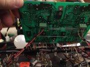
Below is a picture of the back of the Control Board with the configuration Tan - Black - Red for E B C, verified that the wires match the pinout on the Q6 transistors.

Below is a picture of the back of the Control Board with the configuration Tan - Black - Red for E B C, verified that the wires match the pinout on the Q6 transistors.

Did you check your chassis without control board installed first to ensure that the chassis alone came up and that you had 0 volts on the output of each channel?
mlucitt
Veteran and General Yakker
Yes, in a fashion. With the B+ and B- (only) disconnected from the Control Board and both rail fuses installed, the chassis comes up with no issues (Dim Bulb stays dim) and the voltage on both outputs is the same, it climbs very slowly and slows and finally stops at +123mV as the amp warms up. This is with nothing connected to the inputs.
The DCP relay kicked in at about 75 on the Variac. and there are no odd smells or smoke, yet.
The DCP relay kicked in at about 75 on the Variac. and there are no odd smells or smoke, yet.
Wattage of bulb on DBT?
mlucitt
Veteran and General Yakker
150W - because I was setting up for a PL700 build.
mlucitt
Veteran and General Yakker
Update. Recall that the Dim bulb stayed dim with everything hooked up to the Control Board except B+ and B- on 12L and 11L. When I connect those rail leads, the dim bulb burns bright.
Today, I left the B+ and B- connected and pulled all the other wires off the bottom of the control board (Q6 transistors still hooked up). Power applied, Dim bulb stayed dim. As I reconnected each wire, the dim bulb stayed dim until I came to 3L (Q12 Base), so I left it unconnected and continued left-to-right. The dim bulb again went bright when 9R (Q11 Base) was connected, so I left it unconnected and continued until all wires were back in there respective spots.
So with either 3L or 9R connected, I get the dreaded bright bulb. Looking at the schematic of the Control Board these connections lead to Q9L and Q6R, I checked and they are the appropriate devices, MJE15035 and MJE15034, respectively. With full AC voltage applied, the measured voltage on 3L was +14.2V and the measured voltage on 9R was -.22V on my digital Fluke. The voltage on 3L seems high...
Just for fun, I measured the disconnected Q12 Base wire (goes to Control Board 3L) and measured -82V (rail), while the other disconnected Q11 Base wire (goes to Control Board 9R) measured -.15V. This seems correct with no inputs connected.
- Joined
- Jan 14, 2011
- Messages
- 75,831
- Location
- Gillette, Wyo.
- Tagline
- Halfbiass...Electron Herder and Backass Woof
So....youve got rail voltage to the base, not good, but you know that...
- Joined
- Jan 14, 2011
- Messages
- 75,831
- Location
- Gillette, Wyo.
- Tagline
- Halfbiass...Electron Herder and Backass Woof
This is Quasi right?? Got D13 in...
Hi Mark
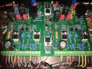
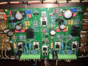
Some good photos of the board front with wires entering it would be good. Similar to the back side of the board that you have shown us.
Some good photos of the board front with wires entering it would be good. Similar to the back side of the board that you have shown us.
mlucitt
Veteran and General Yakker
This is Quasi right?? Got D13 in...
Yes, quasi on this one. Both D13L and D13R are in place with the proper orientation.
mlucitt
Veteran and General Yakker
mlucitt
Veteran and General Yakker
So....youve got rail voltage to the base, not good, but you know that...
Not the best looking scan of the original PL400 schematic (attached), but if you look in the blue box, toward the bottom, you see Q7 Collector leading up to the Base of Q12. It looks to me like there is -79V on Q7 Collector which puts close to rail voltage on the Base of Q12, along with -79.5V on the Emitter of Q12, and on the Collectors of all the other minus side output transistors - Q14, Q16, and Q18 via R37 (150 Ohms). They have negative rail voltage sitting on the Emitters, so they are not biased to conduct with no input signal. At least that is how I understand it.
All four of my drivers are MJ21196G, is that OK? I had missing RCA 410's, so all 16 transistors on the back are the same.
Attachments
Last edited:
- Joined
- Jan 14, 2011
- Messages
- 75,831
- Location
- Gillette, Wyo.
- Tagline
- Halfbiass...Electron Herder and Backass Woof
No, you need different drivers than outputs. I'll send some 410's...
mlucitt
Veteran and General Yakker
I tested the MJ21196G transistors that I was using as drivers Q11 and Q12 on both sides, they tested good. I will try powering up the amp on the DBT with them removed and see what happens.


