I'm Buying a "Mule" PL400

Gepetto

Administrator
Staff member
Joined
May 15, 2011
Messages
13,536
Location
Sterling, MA
Tagline
Old 'Arn Enthusiast
Hi Mark
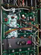
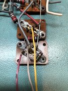
In your photo above labeled Left Bottom.jpg It seems you have 2 wires exiting the collector of Q12. The wiring on all the PL400 harnesses I possess have only ONE wire exiting the collector of Q12 and that wire goes to pin 6 of each channel (photo below of original PL400 harness). What is the second wire and where is it going to? Red wire goes to Pin3, Yellow wire goes to Pin4 and Gray wire goes to Pin6. IMG_1068.JPG
 
Last edited:

Gepetto

Administrator
Staff member
Joined
May 15, 2011
Messages
13,536
Location
Sterling, MA
Tagline
Old 'Arn Enthusiast
I have a similar question on the right channel picture as well Mark. Not sure where the second wire is heading to.
 

mlucitt

Veteran and General Yakker
Joined
Jun 24, 2011
Messages
3,367
Location
Jacksonville, FL
Hi Mark
In your photo above labeled Left Bottom.jpg It seems you have 2 wires exiting the collector of Q12. The wiring on all the PL400 harnesses I possess have only ONE wire exiting the collector of Q12 and that wire goes to pin 6 of each channel (photo below of original PL400 harness). What is the second wire and where is it going to? View attachment 36263
That additional wires are for the output to the meters and they are not presently connected to anything. I moved the meter outputs to the bottom of the transistor buss bars so that I could lead the wires to the Faceplate from the bottom instead of the top. If you think this could be an issue, I can clip them off at the transistor pads.
 

mlucitt

Veteran and General Yakker
Joined
Jun 24, 2011
Messages
3,367
Location
Jacksonville, FL
Thanks Mark. That points to a good control board doing its job. The resistors you installed simulated the output stages that are external to the control board.
I figured the Control Board was probably good. Now, I need to find out why the amplifier is drawing so much current at idle. If I put in just the driver transistors and bring it up to full operating voltage on the Variac, what is the worst case scenario? Is there any chance the Control Board will be damaged?
 

Gepetto

Administrator
Staff member
Joined
May 15, 2011
Messages
13,536
Location
Sterling, MA
Tagline
Old 'Arn Enthusiast
I figured the Control Board was probably good. Now, I need to find out why the amplifier is drawing so much current at idle. If I put in just the driver transistors and bring it up to full operating voltage on the Variac, what is the worst case scenario? Is there any chance the Control Board will be damaged?
Not sure I recommend that Mark...
 

Gepetto

Administrator
Staff member
Joined
May 15, 2011
Messages
13,536
Location
Sterling, MA
Tagline
Old 'Arn Enthusiast
Not your problem Mark but asking a question. Why is a wire heading south out of the thermoswitch in the middle of the backwall? The wires in and out of the thermoswitch should be tightly paired together to maximize hum generation in the amp. AC wiring should be all by itself and not close to any DC wiring. I think I have a picture somewhere in my archives. IMG_0751.JPG
 

mlucitt

Veteran and General Yakker
Joined
Jun 24, 2011
Messages
3,367
Location
Jacksonville, FL
Not your problem Mark but asking a question. Why is a wire heading south out of the thermoswitch in the middle of the backwall? The wires in and out of the thermoswitch should be tightly paired together to maximize hum generation in the amp. AC wiring should be all by itself and not close to any DC wiring. I think I have a picture somewhere in my archives. View attachment 36265
Joe, a good question. I had to replace that wire due to poor insulation and I temporarily routed it down the side of the chassis and along the bottom, then up to the thermoswitch. I plan to route it along the original path as soon as I get the amplifier sorted out.
 

mlucitt

Veteran and General Yakker
Joined
Jun 24, 2011
Messages
3,367
Location
Jacksonville, FL
Not sure I recommend that Mark...
Just my frustration coming out, Joe.
Are there any voltage or continuity checks I can make on the chassis to narrow down the source of the issue? I have checked all the point-to-point wiring and it shows zero resistance. Nothing on the chassis is grounded that should not be.

If I pull the -80VDC fuse, the DBT is normal. This would seem to indicate the path of the excessive current is on the negative rail. If I pull both the Q12 drivers, the DBT is normal. This indicates the problem is in the Class A part of the amplifier. From there, I'm lost.
 

Gepetto

Administrator
Staff member
Joined
May 15, 2011
Messages
13,536
Location
Sterling, MA
Tagline
Old 'Arn Enthusiast
Sex is right Mark. Did you try one channel only with the SJ2741 in the lower spot? Easier to trouble shoot if you bring it down to one channel only.

Pull the drivers out of the other channel and just focus on one channel until you get success
 

mlucitt

Veteran and General Yakker
Joined
Jun 24, 2011
Messages
3,367
Location
Jacksonville, FL
After way too much wrangling with this PL400. I am throwing in the towel.

Thanks to Joe, I know the new WO Control Board is good. I have tried every trick I know and I cannot get the components on the backplane to work together and play nice. I have checked polarity on everything, I have re-flowed every solder connection, I have verified every mechanical connection, I have run continuity on every wire, I have tested every component in and out of circuit, and I have checked for shorts at each junction. I am starting to think there might be a ball of solder squished between the metal chassis and a transistor mount. Just can't get the DBT to work with the outputs populated, drawing too much current when powered on.

So, I am going to strip the amplifier and install the new PL400 Backplane Boards. While I am at it, I will go full complementary with the output transistors to squeeze the best possible sound out of this amplifier.

Thoughts?
 

mlucitt

Veteran and General Yakker
Joined
Jun 24, 2011
Messages
3,367
Location
Jacksonville, FL
Let us know what the short is....if ya find it...that shit drives me nuts...
I have passed the "nuts" stage and moved to "drinking to numb the pain" and then on to "talking to my imaginary friend" regarding the possibility of electrons piling up on top of each other when the wire colors are too dark.
 
Top