Don Imlay's Phase Linear 400 Series II Quasi -Comp.

After spending just 2 minutes with the 5088's I knew the lead situation is going to be even worse with these. The 2N3403's have a pretty stiff lead. Good for maybe 10-15 flexions. The 5088's MAYBE 5. Herein is offered a solution to this problem. Not knowing if Don was OK with epoxy on his Lassie's chassis (this one is "Kay" btw), a mechanical option was preffered.

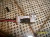
1/16 inch aluminum. Hand cut to shape and burrs filed off. A 4-40 machine screw mikes at .104. A #36 drill mikes at .106. Cable tie around the bottom of the "L" section. Voila'
 

Attachments

  • 107_1766.JPG
    107_1766.JPG
    832 KB · Views: 144
  • 107_1765.JPG
    107_1765.JPG
    729 KB · Views: 145
  • 107_1764.JPG
    107_1764.JPG
    742.9 KB · Views: 141
I believe we are ready to test. VERY EFFECTIVE lead stabilizers.
 

Attachments

  • 107_1769.JPG
    107_1769.JPG
    750.4 KB · Views: 136
  • 107_1768.JPG
    107_1768.JPG
    610.9 KB · Views: 142
  • 107_1767.JPG
    107_1767.JPG
    652.1 KB · Views: 134
About as uneventful power up as you can get.
Offset---.006mv left, .012mv right.
Unloaded clip----448@200 hz
421@ 2000hz
390 @ 20,000hz

Loaded clip-----305 @ 200 hz
302 @ 2000hz
2987 @ 20,000 hz.

All into 8 ohms with both loaded and driven

THD& N
RCA-410 drivers, MJ 21196 outputs. 8 ohm loads. Bias 342 left, 345 right.
Input voltage 250mv, I 1KHZ input freq
Before(with stock board)--- .0605%
After with WOA board-------.0394%
Pics of THD & N sweeps, 10 HZ to 80,000 Hz, unweighted, Input voltage 250 mv
Sweep made with 150 steps, slow, range from .0010 % to 1 %
 

Attachments

  • 107_1770.JPG
    107_1770.JPG
    721.7 KB · Views: 123
  • 107_1771.JPG
    107_1771.JPG
    778.7 KB · Views: 118
  • 107_1772.JPG
    107_1772.JPG
    650.2 KB · Views: 127
  • 107_1773.JPG
    107_1773.JPG
    644.6 KB · Views: 127
  • 107_1774.JPG
    107_1774.JPG
    780.1 KB · Views: 114
Yeah, your analyzer is awesome. And in thhe hands of someone wheo knows how to use it, it must be fun as hell. So are Phas Linear 400 Series II going to be a viable rebuild amp? Are they going to perform at the level of the Series I? I know you said the bean counters had made the component quality dive, but some of those things can be changed. Were there any real improvements to the circuit from the SEries I, or are they mostly cosmetic and economic? Just interested in whaat your overall take on these amps might be. How about the DRS Series? Anything worth rebuilding there? How about a Dual 500? Worth the effort? What would one of them do after a rebuild....600 Watts per, or more? Worth the efort to get one that would work?
 
Hi Lee
I generally downsize the bias transistor wiring to M22759/16-26 26AWG Tefzel or equivalent Teflon if you have it (that is what led to the smaller holes on the PCB). The original wiring that Phase used was large structural overkill for this purpose (but they probably wanted the production efficiency of using one wire size) and the insulation has become brittle over time. This wire works much better for the bend loop that you have to use to install the bias transistor.
 
It now has #24 Stranded, fairly flexible wire. I agree the factory stuff was dangerous to the leads even when new. It's standard practice here Joe to replace it, should have replaced it sooner than I usually do.
The RCA-410's are coming out and some repeat THD & N measurements then some 21194's. Should be interesting.
Sutton the only changes I see on the PL 36 board were the Op-amps replacing the discreet front end. These early op-amps were noisier than a discreet so as to the "why" we are left to wonder.
On a side note. The protection circuitry was first published by a semiconductor manufacturer a few years before Phase starting using it. Gerald Edward Stanley of "Crown" fame was contemplating a lawsuit against Phase for using that circuit buy it was determined in court the general idea had been in the public domain for some time.

Yeah guys, AWESOME analyzer.
 
Mark, there are a number of filters built in and a bunch you can install in spare slots. This sweep was done from 10 hz to 80,000 hz UNWEIGHTED. That top reading of .267 was at 80,000hz at .254 volts input with a corresponding 10 watt output. A neat thing about after the sweep is taken is you can move your cursor over any sampled frequency and it recalls the data.
 
Joe, it appears the 2N5088's have the range and resolution to work with no changes to the supporting circuitry, nicely done.
 
Lee, I guess that was my point. Human hearing fades at 20,000 and I'm not really sure about the "harmonics" theory if you can't hear them anyway, there is no impact. Personally, my hearing is junk above 18,000. I would like to know how the THD improves if you come down to a realistic cutoff of 20,000 or even 40,000. To mak an audio amp drive 80,000 is kinda hard when you consider that it also has to drive 20 Hz. Just a thought, we are conditioned to 20-20K and it would be nice to compare apples to apples.
 
I will be sampling the MPSA18 and the BC550B in that same application Lee as well. I already use the MPSA18 in the front end and will soon be sampling the BC550B devices as well. Both lower noise and higher Vceo than the original TIS97 devices.
 
mlucitt said:
Lee, I guess that was my point. Human hearing fades at 20,000 and I'm not really sure about the "harmonics" theory if you can't hear them anyway, there is no impact. Personally, my hearing is junk above 18,000. I would like to know how the THD improves if you come down to a realistic cutoff of 20,000 or even 40,000. To mak an audio amp drive 80,000 is kinda hard when you consider that it also has to drive 20 Hz. Just a thought, we are conditioned to 20-20K and it would be nice to compare apples to apples.


Mark an amp has to be designed to go out to 80k because of something to do with unity gain and artifacts dominating if not. I'll look that up.
 
It appears the 15024's exhibit less distortion. The test conditiuons were the same, I randomly picked 4 150245's out of a hundred with a 1025 date code.
 

Attachments

  • 107_1775.JPG
    107_1775.JPG
    820.5 KB · Views: 86
  • 107_1776.JPG
    107_1776.JPG
    724 KB · Views: 78
  • 107_1777.JPG
    107_1777.JPG
    700.6 KB · Views: 76
  • 107_1778.JPG
    107_1778.JPG
    702 KB · Views: 75
  • 107_1779.JPG
    107_1779.JPG
    703.6 KB · Views: 74
  • 107_1780.JPG
    107_1780.JPG
    723.5 KB · Views: 78
  • 107_1781.JPG
    107_1781.JPG
    805 KB · Views: 74
More pics.
 

Attachments

  • 107_1782.JPG
    107_1782.JPG
    693.5 KB · Views: 81
  • 107_1786.JPG
    107_1786.JPG
    1.6 MB · Views: 79
  • 107_1787.JPG
    107_1787.JPG
    1.5 MB · Views: 75
  • 107_1788.JPG
    107_1788.JPG
    1.6 MB · Views: 76
  • 107_1789.JPG
    107_1789.JPG
    1.4 MB · Views: 73
  • 107_1790.JPG
    107_1790.JPG
    1.8 MB · Views: 75
Joe, I've noticed a relationship between distortion and bias, naturally, but my question is: Is the reason distortion is less at a greater output because of the additional bias required for that additional output??
 
It's snowing outside and the Jazz has an attitude, it was like spring yesterday. I think she thought summer was supposerd to be here today.
 

Attachments

  • 107_1791.JPG
    107_1791.JPG
    1.5 MB · Views: 81
Hi Lee
The distortion is higher at lower outputs due to the fact that the A-B crossover distortion is a larger percentage of the overall signal amplitude. At higher output amplitudes, the crossover distortion is a tiny blip that exists for a tiny percentage of the overall signal

Conversely as you dial down the amplitude to approach zero, eventually the crossover distortion will be a very significant percentage of the signal.

The bias is close to constant, regardless of the output level, that is the job of Q6 to make it constant. The only thing that is not constant about the bias is its dependence on temperature. As the amp heatsink heats up, the bias is reduced in response to that temperature rise because the base-emitter forward junction voltage of all the output devices is likewise reduced. The function of Q6 is to detect that temperature rise and to reduce the bias current with temperature to prevent thermal runaway of the output stages.

You can see the effect of bias on distortion at a constant 1W output. Increase the bias to 0.400V and the distortion will go down. Decrease it to 0.300V and the distortion will go up.

This bias is what makes it a class A-B amplifier.
 
Oh yes i played with that quite a bit. What was your guesstimate on the range of the 5088 for bias current??
 
guessing .250 to .450 but that is just a wild ass guess. Been a while since I was in there.
 
Back
Top