- Joined
- Jan 14, 2011
- Messages
- 75,459
- Location
- Gillette, Wyo.
- Tagline
- Halfbiass...Electron Herder and Backass Woof
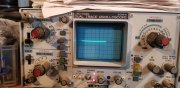
A Fluke 179...

Only thing that stands out to me is I still think the LED transistor, if it is a TIS97 is in backwards or somehow not compatible with the original GES97 in this specific application. I searched some for the pinouts and can find nothing on the net. Other than Grapplesaws post that the pinouts are reversed, I can find no specifics. Maybe he can comment. Wanted to sit down and look at the schematic to see how the TIS and GES 97s are implented but have no time.Me too Bill!!! Thanks..
After being on awhile minus 15 and plus 25..
![IMG_4014[1].JPG](https://forums.phxaudiotape.com/data/attachments/43/43543-65554e6861d145d4b3dbe253a051274b.jpg?hash=ZVVOaGHRRd "IMG_4014[1].JPG")
Phase Linear and grounding issues, who would have guessed. I think I'll try this on my PL2000 next time I get it on the bench.
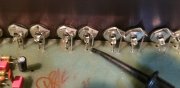
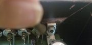
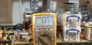
First pic, ground, 2nd pic right L bracket, 3rd pic meter reading.
Far left L bracket 0, middle L bracket 0..
Ground is common input ....
What's up with the 2 resistors coming off the ground trace in your pic?