mlucitt
Veteran and General Yakker
Thanks, Joe.
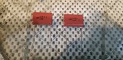
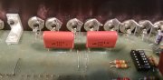
Lee when you get that PL2000 dialed in, are you going to put it on the AP? Maybe take a DC millivolt reading on the outputs, in front and behind those DC blocking caps; just for fun.
Lee when you get that PL2000 dialed in, are you going to put it on the AP? Maybe take a DC millivolt reading on the outputs, in front and behind those DC blocking caps; just for fun.