- Joined
- Jan 14, 2011
- Messages
- 75,446
- Location
- Gillette, Wyo.
- Tagline
- Halfbiass...Electron Herder and Backass Woof

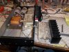
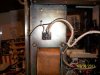
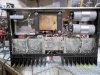
The culprits, unfortunatly, the same outputs used by the Pioneer SX 1980, so all spares have been scarfed up years ago. There is a seller on e-bay selling these for 70.00 a pair, and they look genuine, hopefully the Edster has some stashed.
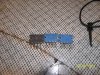
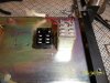
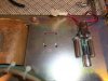
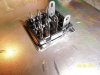
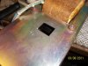
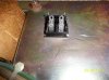
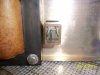
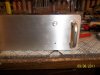
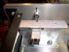
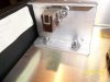
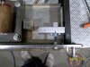
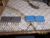
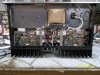
Cory had requested an on/off switch and I had originally talked him out of it. All the pushbuttons I have are only rated for 3 amps at the most. Soooo, that would require a relay, and a mount, and some rewiring, QUIT BEIN A PUSSY LAATSCH AND DO IT!!! OK, OK, drilling holes in faceplates is tedious... QUIT BEIN A PUSSY LAATSCH AND DO IT!!... So, I'm gonna do it. layed out the cut for the relay socket and for the button hole in the faceplate. The button will be inline with the on/off LED. The relay is a 120 volt coil, 10 amp rated contacts, which I will parallel to split the load.
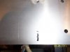
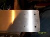
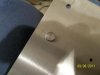
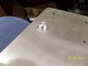
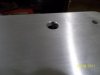
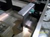
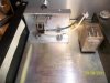
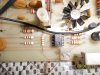
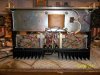
Pilot hole drilled in faceplate. The button mikes at .382, the closest drill is 25/64.The question is, go smaller in case there's a problem you have enough meat left to straighten it out and risk taking too little on the last cut and hang up and make a bigger mess?? OR NUT UP AND TAKE THE SHOT???? Go for it. It's a neater cut going one time, and also irreversible.