Cory's Phase Linear 300 Ser II

Hi Lee
I saw that post but could not tell what the oscillation frequency was. The scope time base sweep wasn't fast enough to be able to measure the fundamental oscillation frequency. You notice that the area where just the predriver was active, the oscillation tamed down a bit. Not gone but less unstable.
 
So the op-amp drops out at the crossover point?? That pic was at 1khz.
 
Ok, in oscillation mode, to identify the oscillation frequency , keep going faster on the timebase till you can see it as a separate entity??
 
Correct Lee, probably if you set your scope to ~1usec per division and trigger on that signal you should be able to see the high frequency sine wave riding on the low frequency sine wave.

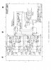
BTW, the LF351 has an odd phase characteristic where the OPA134 has a classic op amp phase characteristic. For example, at 1MHz, the LF351 has approximately 75 degrees of phase LEAD versus the OPA134 which has approximately 110 degrees of phase LAG. This is a very large difference and goes a long way to explaining the unstable behavior. I will have to look at the schematic for the PL300.

To answer your other question, the op amp is still in during that quieter crossover region but the final driver drops out and you are driving the load through the base emitter resistor of the final driver during that short period using the predrivers.
 
Why don't the pre-drivers kick back during the quiet region? They have to change over just like the finals, correct?
 
So, with the feedback circuit set for the 351's characteristics, it's not playing well with the 134???
 
Correct Lee, while the OPA has a classic phase response, the PL300 is evidently set up to take advantage of the unusual phase characteristics of the LF351.

The predrivers are still oscillating, you can see it at a lower amplitude during the crossover region. The series ~10 ohm resistor that the predriver is driving the load with kills a bit of the gain so it is more stable but not completely stable.
 
Ah.....it's faux stable. Just not enough gain to get all worked up about eh?? Would the TL-071 be better??
 
Hi Lee
No the TL-071 would be worse. It is a slightly quieter op amp but has a lower GBW product than the LF351 and has the same classic phase response that the OPA134 had. It will be a no go based on a quick data sheet scan.
 
Instead of listing what won't work, what will?? oR IS THERE no sub for it??
 
Do you have the schematics Lee? I am pretty sure it could be recompensated for use with other op amps.

The phase response for the LF351 is very unique. Most op amps have a simple 90 degree phase lag strategy and no lead, not the LF351.
 
Yeppers----
 

Attachments

  • PL 300 Schematic.jpg
    PL 300 Schematic.jpg
    93.6 KB · Views: 49
Thanks Lee, it looks like there might be some things to try out. It would be good to know the frequency you see it oscillating at (guessing it is pretty high frequency from your scope shot).

One easy thing that should be done is a 0.01uF cap across C102, the 100uF 6.3V cap. Another 0.01uF cap should be placed from pin 7 to pin 4 of the op amp very close to the socket pins (backside of board opposite the socket on the comp side).

Baby steps, one thing at a time. We will attempt the more challenging things after we find out if these have an effect or not. The OPA134 is a very high performance op amp so will be more sensitive to stray parasitic capacitance on that old board layout and is more demanding of proper decoupling.
 
Ok, Joe the PL 300 just arrived at Cory's door an hour ago.SO I have nothing to experiment with. I didn't know how long or IF there was a sub so I shipped it Monday morning. I told him if iot acts up send it back, or I would send him some op-amps. I did put sockets in. I sent it with the LF-351's in.
 
Joe, on Ed and I's last phone call he had a question for you. On the 700B's there were 2 silkscreen patterns. One with the -20db marking on the meter sensitivity adjustment on the left and the other on the right. Depending on which switch was used, they could be wired to work either way. The wafer style would seem to be easy, the other not so. The question----" Do you know of a way to wire the other style switch to work backwards "??
 
I seem to have an example of each in the cave right now.
 

Attachments

  • 100_1223.jpg
    100_1223.jpg
    111.4 KB · Views: 39
  • 100_1222.jpg
    100_1222.jpg
    113 KB · Views: 43
  • 100_1219.jpg
    100_1219.jpg
    92.4 KB · Views: 46
Good to know Lee, I was not aware that Phase made 2 different faceplates to accommodate the switch differences. Thanks for pointing that out, never would have guessed that. Yes I have worked through swapping the switch to work the other way with a guy about 6 mos ago. I have some photos. The switch worked backwards from the faceplate legending and he wanted it to work per the lettering (can't blame him for that)

Sutton has one of the wafer switches but I do not know which faceplate he has to go along with it. When Sutton gets back into working on it, we can confirm which orientation he has on his 700B.
 
Hi Lee
Although I have not tried it, I believe the switch operation theory on this switch (that you have pictured) is the same as the wafer switch is.
If you want to swap the rotation orientation:

1) Remove the orange wire and the bus wire jumper between 2 terminals shorted by the bus wire. This will leave 2 open solder lugs.
2) Move the Blue wire clockwise by one lug into the open solder lug that used to have the orange wire in it (rearmost lug in your picture).
3) Move the Yellow wire clockwise by one lug into the second open solder lug that used to have the non-orange end of the bus wire in it (frontmost lug in your picture).
4) Solder the orange wire and bus wire to the 2 now open solder lugs that used to be occupied by the Blue and Yellow wires.

That should do it. The switch should now have reversed the -20dB function with respect to the meters.

I suppose we should drop this into the WOPL section for reference.
 
Back
Top