Q4 the MPSA92/93Thank you! It did not occur to me that a transistor would be inside that backet. I know those things as Loomis Clips.
If that's where the 2N5088's go, which transistors get these heatsinks?
View attachment 14184

You are using an out of date browser. It may not display this or other websites correctly.
You should upgrade or use an alternative browser.
You should upgrade or use an alternative browser.
700B blew one Right channel 5A supply fuse
- Thread starter 62vauxhall
- Start date
- Joined
- Jan 14, 2011
- Messages
- 75,789
- Location
- Gillette, Wyo.
- Tagline
- Halfbiass...Electron Herder and Backass Woof
Your in the best hands there are now Gary...
It sounds like your goody box was packed full of good stuff.
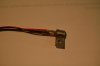
Here's a bit of information regarding the bias transistor bracket:
The tunnel where the transistor legs are soldered to the hook up wires is fairly tight so the technique I've used is shown in the following photos. I tin the wires and the transistor legs prior to soldering. The wires are placed in parallel with the legs and carefully soldered in place. The joints are then covered with heat shrink and I'll do a quick check to validate no shorts and that the transistor checks out good with the meter in the diode test mode.
This bracket was designed with the intent of moving the stress point away from the transistor leg/wire joint and to the wires after the tie point in addition to protecting the transistor legs from damage.
Attachments

Last edited:
62vauxhall
Veteran and General Yakker
- Joined
- May 14, 2014
- Messages
- 2,365
- Location
- Southwest Kootenays BC
- Tagline
- No such things as bad days, just bad moments
Understood. A picture is worth a thousand words. I'll do that first before anything else on the board.
62vauxhall
Veteran and General Yakker
- Joined
- May 14, 2014
- Messages
- 2,365
- Location
- Southwest Kootenays BC
- Tagline
- No such things as bad days, just bad moments
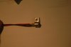
Since I was going to need some thermal compound for the heatsinks, I asked for some in an electronic parts store. They sold me this:


Its called Stars DRG-102 and all the label "fine print: is Chinese. In hindsight, I'm wondering if it's the right stuff? It's grey not white and looking online, it's referred to as thermal adhesive glue containing 50% silicone - 30% carbon compounds - 20% metal oxide. Those ingredients sound electrically conductive. Is it OK to use provided none gets in contact with any pins or, should I get the white greasy stuff on Monday?
Also wondering about the power transistor insulators I was sent. Presumably, I'm to use them in lieu of the clear (mica?) ones that are already there?
If I am to use those new insulators, am I also supposed to use thermal compound as well? And if so, can I use that grey stuff?
- Joined
- Jan 14, 2011
- Messages
- 75,789
- Location
- Gillette, Wyo.
- Tagline
- Halfbiass...Electron Herder and Backass Woof
Those grey Sil-Pads do not require the mica insulators or the heatsink grease. You were right in asuming you got the wrong stuff, but it's a moot point. No longer needed....
- Joined
- Jan 14, 2011
- Messages
- 75,789
- Location
- Gillette, Wyo.
- Tagline
- Halfbiass...Electron Herder and Backass Woof
Understood. A picture is worth a thousand words. I'll do that first before anything else on the board.
You are now one of 7 people on the planet with FaboNav's Deluxe Model 2 bias tranny brackets....you rock...
62vauxhall
Veteran and General Yakker
- Joined
- May 14, 2014
- Messages
- 2,365
- Location
- Southwest Kootenays BC
- Tagline
- No such things as bad days, just bad moments
I am indeed honoured to have those brackets!
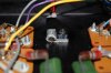
Also puzzled. I identified transistors comparing their actual part number to what's on the schematic and Q1 through Q10 match. But there are (3) 2N5401's and (1) MPA56. Is the latter a substitute for the former - are they interchangeable?
Also, I can't find these two transistors on the schematic. The one with number to the camera is MPSU60 and the other (green/red/orange stripes) is MPSU10. Do I just ignore these and leave them be? Are they a post schematic modification?

Looks to me that Q11 and higher are those on the main heatsink,
Also puzzled. I identified transistors comparing their actual part number to what's on the schematic and Q1 through Q10 match. But there are (3) 2N5401's and (1) MPA56. Is the latter a substitute for the former - are they interchangeable?
Also, I can't find these two transistors on the schematic. The one with number to the camera is MPSU60 and the other (green/red/orange stripes) is MPSU10. Do I just ignore these and leave them be? Are they a post schematic modification?
Looks to me that Q11 and higher are those on the main heatsink,
Last edited:
Since I was going to need some thermal compound for the heatsinks, I asked for some in an electronic parts store. They sold me this:
View attachment 14213View attachment 14214
Its called Stars DRG-102 and all the label "fine print: is Chinese. In hindsight, I'm wondering if it's the right stuff? It's grey not white and looking online, it's referred to as thermal adhesive glue containing 50% silicone - 30% carbon compounds - 20% metal oxide. Those ingredients sound electrically conductive. Is it OK to use provided none gets in contact with any pins or, should I get the white greasy stuff on Monday?
Also wondering about the power transistor insulators I was sent. Presumably, I'm to use them in lieu of the clear (mica?) ones that are already there?
If I am to use those new insulators, am I also supposed to use thermal compound as well? And if so, can I use that grey stuff?
The Stars DRG-102 compound would not work in this application as Lee said. The carbon compounds and metal oxide are conductive and would cause a major failure. The two legs coming out of the TO-3 package are the base and emitter - the case is the collector and must be electrically isolated from the chassis. The Sil-pads Lee sent you are very user friendly and have similar thermal transfer characteristics as the mica with non-conductive silicon based thermal compound. There is a torque spec with these pads and they are a one time use.
62vauxhall
Veteran and General Yakker
- Joined
- May 14, 2014
- Messages
- 2,365
- Location
- Southwest Kootenays BC
- Tagline
- No such things as bad days, just bad moments
The Stars DRG-102 compound would not work in this application as Lee said. The carbon compounds and metal oxide are conductive and would cause a major failure. The two legs coming out of the TO-3 package are the base and emitter - the case is the collector and must be electrically isolated from the chassis. The Sil-pads Lee sent you are very user friendly and have similar thermal transfer characteristics as the mica with non-conductive silicon based thermal compound. There is a torque spec with these pads and they are a one time use.
Understood and have dismissed the notion of using thermal compound since those Sil-pads make it unnecessary.
If you have any thoughts on my previous post, I'm all ears.
Understood and have dismissed the notion of using thermal compound since those Sil-pads make it unnecessary.
If you have any thoughts on my previous post, I'm all ears.
It seems that those transistors are not original components. You should be able to use the service manual to determine what transistors those are by using the board layout drawing. There are several variants of the board so make sure you're using the correct one. After you determine the component nomenclature you can cross reference it using the correct schematic. BTW what board type do you have?
Lee will have to chime in but I believe that he provided you with replacement transistors for most if not all of the ones you have on the driver board and he included the bias transistors. From the schematic Q11 through Q16 and Q18 through Q23 are the TO-3's located on the chassis heat sinks - Q17 is on the driver board. FYI - the components within the dashed lines are located on the driver board.
Edit: Lee posted the correct schematic and the output TO-3's are Q-11 through Q22.
Last edited:
- Joined
- Jan 14, 2011
- Messages
- 75,789
- Location
- Gillette, Wyo.
- Tagline
- Halfbiass...Electron Herder and Backass Woof
Thanks Navo . Gary, ignore what was on the board before . If you replace the tyranny's as I put on the list it will be fine. Could you post a pic of the parts layout drawing you are using. There is being some confusion generated.
62vauxhall
Veteran and General Yakker
- Joined
- May 14, 2014
- Messages
- 2,365
- Location
- Southwest Kootenays BC
- Tagline
- No such things as bad days, just bad moments
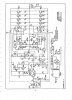
Thanks. There is confusion and I confuse easily. The manual was downloaded from HiFi Engine and schematics are on pages 9, 11 and 13.
Counting the bias transistors there are 11 transistors on my board. There are three schematics drawings in the manual and only one has 11 transistors, the others have 10.
I should have picked up on this tidbit of information earlier because I was following what looked to be the original schematic on page 13 with 10 transistors. The additional transistor, marked Q1 is on the page 9 diagram which I guess now superseded the others. A transistor in that position does not appear in the other diagrams and since it's called Q1, throws the numbering system out of whack. They should have called it Q11 and not bumped the other position numbers up by 1.
These are the schematic and layout drawings that contain 11 transistors. I assume now that since it has 11 transistors, I should be following it. There appear to be some typos on it and the printing is not clearly legible.
Adding to my confusion, the diagram identifies Q1 as T1 and I see no such transistor on the board.
View attachment Phase Linear 700B 11 transistor schematic.pdf.pdfView attachment Phase Linear 700B 11 transistor diagram.pdf.pdf
- Joined
- Jan 14, 2011
- Messages
- 75,789
- Location
- Gillette, Wyo.
- Tagline
- Halfbiass...Electron Herder and Backass Woof
That is the parts layout for the PL 0171 board used in 700 Series I's. I'll post the Pl14 layout...
- Joined
- Jan 14, 2011
- Messages
- 75,789
- Location
- Gillette, Wyo.
- Tagline
- Halfbiass...Electron Herder and Backass Woof
The schematic also refers to the PL 0171 board. I'll post the correct schematic and layout for the board for which you posted pics of earlier...
- Joined
- Jan 14, 2011
- Messages
- 75,789
- Location
- Gillette, Wyo.
- Tagline
- Halfbiass...Electron Herder and Backass Woof
- Joined
- Jan 14, 2011
- Messages
- 75,789
- Location
- Gillette, Wyo.
- Tagline
- Halfbiass...Electron Herder and Backass Woof
I am indeed honoured to have those brackets!
Also puzzled. I identified transistors comparing their actual part number to what's on the schematic and Q1 through Q10 match. But there are (3) 2N5401's and (1) MPA56. Is the latter a substitute for the former - are they interchangeable?
Also, I can't find these two transistors on the schematic. The one with number to the camera is MPSU60 and the other (green/red/orange stripes) is MPSU10. Do I just ignore these and leave them be? Are they a post schematic modification?
View attachment 14241
Looks to me that Q11 and higher are those on the main heatsink,
The MPSU 60 is in Q7's spot. The one with the stripes is in Q10's spot....
62vauxhall
Veteran and General Yakker
- Joined
- May 14, 2014
- Messages
- 2,365
- Location
- Southwest Kootenays BC
- Tagline
- No such things as bad days, just bad moments
OK, thanks - think I got it.
Just to be absolutely, positively, 100% sure before I start, do I follow the pin out of the old transistors?
Just to be absolutely, positively, 100% sure before I start, do I follow the pin out of the old transistors?
- Joined
- Jan 14, 2011
- Messages
- 75,789
- Location
- Gillette, Wyo.
- Tagline
- Halfbiass...Electron Herder and Backass Woof
Is it making sense now??
- Joined
- Jan 14, 2011
- Messages
- 75,789
- Location
- Gillette, Wyo.
- Tagline
- Halfbiass...Electron Herder and Backass Woof
OK, thanks - think I got it.
Just to be absolutely, positively, 100% sure before I start, do I follow the pin out of the old transistors?
NO!!! On Q5, Q7, Q10 YES!!! On the TO-92's there are going to be different pinouts. Download the data shetts for the TIS-97's, 93's and MPSA 93 .. Follow those. Study the schematic and correlate to the pinouts. I have personally beat my head against the wall for days over that one. Transposing pinout from switching from looking at the top of the board to the bottom can and does happen. I have a PL14 board here if you have trouble figuring it out.