AngrySailor
Veteran and General Yakker
- Joined
- Oct 15, 2014
- Messages
- 3,419
- Tagline
- ---not quite right

No, 350mV both sides.Did you have to readjust bias?

The meter leads are supposed to come in on the same edge of the board as the 2 white ground wires are.No, 350mV both sides.
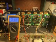
Here’s a pic of light board. The screw driver points to the meter input leads from the speaker outputs. By removing both 10 resistors, the circuit will be open. View attachment 57034

They would have to be jumped in place of one resistor each side so top to bottom to complete the circuit. Will this overload the meters as you’re removing 5 ohm of resistance.Remove the resistors, then jump the holes on top that are not connected.

Here’s the backside of the light board. As you can see removing the parallel 10 ohm resistors breaks the circuit. Those pads go nowhere but through those two resistors and on to the meter through then 23k and a diode, then through the meter to ground.
Fug forgot pic. View attachment 57035
Ok so that’s the same as a jumper wire. What about removing that 5 ohm resistance? Meters be ok? They were sluggish before, hardly moved...

")

")
