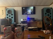
700/1 “Tim” WOPL driver board

AngrySailor

Veteran and General Yakker
Joined
Oct 15, 2014
Messages
3,419
Tagline
---not quite right
Hey joe remember a while back we talked about LED meter lights for the 700/1. There are only two bulbs per meter in these but it would be very simple to drill more holes in the bottom of the meter case. I’d use a drill sharpened for plastics to avoid breakage for sure but think that would work? They’re very dim with 2x 6v incandescents in there...
 

AngrySailor

Veteran and General Yakker
Joined
Oct 15, 2014
Messages
3,419
Tagline
---not quite right
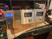
Just going through some final checks. DC offset 1mV each side, bias hovering right around 350mV just letting it idle on the bench for a bit check final setting. Everything seems ok so far... just plugged the signal generator in and gave things a little signal. Both meters rose evenly. 7835C0B9-6544-43E6-BAC1-838EFC197F0C.jpeg
 

George S.

Veteran and General Yakker
Joined
Feb 18, 2020
Messages
4,539
Hey joe remember a while back we talked about LED meter lights for the 700/1. There are only two bulbs per meter in these but it would be very simple to drill more holes in the bottom of the meter case. I’d use a drill sharpened for plastics to avoid breakage for sure but think that would work? They’re very dim with 2x 6v incandescents in there...
I replaced the incandescent bulbs in my garage system Optimus MPA-200 power amps years ago with a simple resistor and LED for each bulb. Each meter takes 2 solder-in bulbs, and the LEDs are so damn bright there's really no reason to add more. Go for it!
 

George S.

Veteran and General Yakker
Joined
Feb 18, 2020
Messages
4,539
Oops, the Optimus amps used DC for the bulbs, that's probably AC on your 700. Consider rectifying it right on the light board with 2 1N4004 diodes.
 
Last edited:

George S.

Veteran and General Yakker
Joined
Feb 18, 2020
Messages
4,539
Andrew, just remembered I have a extra WOAD 400 S1 LED light board that I'll never use. Maybe you can mod it to work. I''ll send it with the other stuff.
 

AngrySailor

Veteran and General Yakker
Joined
Oct 15, 2014
Messages
3,419
Tagline
---not quite right
Andrew, just remembered I have a extra WOAD 400 S1 LED light board that I'll never use. Maybe you can mod it to work. I''ll send it with the other stuff.
Thanks!

I’ve repaired the crossover, just hooking Tim up now for a test drive... fingers crossed!
 

George S.

Veteran and General Yakker
Joined
Feb 18, 2020
Messages
4,539
Or strip the components you need off it and add to your board. Probably easiest. Cool white LEDs. Your sound stage looks awesome. Wonderful you can share it with your father. Enjoy! Later.
 

AngrySailor

Veteran and General Yakker
Joined
Oct 15, 2014
Messages
3,419
Tagline
---not quite right
Or strip the components you need off it and add to your board. Probably easiest. Cool white LEDs. Your sound stage looks awesome. Wonderful you can share it with your father. Enjoy! Later.
Thanks. On the list is a wood cabinet to hold the gear and shelves for records. Eventually!
 

AngrySailor

Veteran and General Yakker
Joined
Oct 15, 2014
Messages
3,419
Tagline
---not quite right
Joe/Lee, still seems the meters read low when the amp clips. Can I swap out them 23k resistors for a lower value to get them to dance a little more?
 

AngrySailor

Veteran and General Yakker
Joined
Oct 15, 2014
Messages
3,419
Tagline
---not quite right
Are ya clipping it?
I would say. Would be nice to know if it’s putting out rated power before things start sounding crunchy... it pretty darn loud but I’m also just taking out a 550wpc QSC I had in while Tim was hurt. Tim’s driving 4x15”, two mids and horns so it’s demanding... Tim’s high passed at 50hz also so not driving the deep lows should save some power there. The big carver and 18” subs do that duty.
 

Gepetto

Administrator
Staff member
Joined
May 15, 2011
Messages
13,473
Location
Sterling, MA
Tagline
Old 'Arn Enthusiast
Joe/Lee, still seems the meters read low when the amp clips. Can I swap out them 23k resistors for a lower value to get them to dance a little more?
Yes, the 700B circuit has a 22K in series with a 1.8K resistor for a total of 23.8K. When the -20dB switch is kicked in, it shorts out the 22K ohm resistor and leaves a 1.8K in series. This is just to give you a reference on how this was accomplished in the later generations.

So somewhere between 2K and 23K is your range to play with.
 

AngrySailor

Veteran and General Yakker
Joined
Oct 15, 2014
Messages
3,419
Tagline
---not quite right
Yes, the 700B circuit has a 22K in series with a 1.8K resistor for a total of 23.8K. When the -20dB switch is kicked in, it shorts out the 22K ohm resistor and leaves a 1.8K in series. This is just to give you a reference on how this was accomplished in the later generations.

So somewhere between 2K and 23K is your range to play with.
Cool bEaNz. I have the 11k resistors from Linda’s old parts. I’ll try them.
 

AngrySailor

Veteran and General Yakker
Joined
Oct 15, 2014
Messages
3,419
Tagline
---not quite right
Andrew, did you modify the resistors on the light board yet??
The Zoebel? That’s gone, I haven’t reduced the series resistance from the 23k yet.
Pounding tunes way to late but hey, I’m unemployed so I’m my own boss rn... giving Tim a work over!

 
Top