AngrySailor
Veteran and General Yakker
- Joined
- Oct 15, 2014
- Messages
- 3,419
- Tagline
- ---not quite right
Thanks Lee, couldn’t have done it without all the help here.As well you should, when messing with the original backplanes that's a win bud!!

Thanks Lee, couldn’t have done it without all the help here.As well you should, when messing with the original backplanes that's a win bud!!
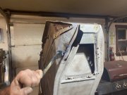
He’s already made a new patch for there. These fenders are near 100 years old, this one is the worse of the pair. Make him start with the nasty one!Poor guy doesn't have much to work with sometimes....
Practice makes perfectguess I’m getting lots! Hopefully got it licked. Might take a break for a bit maybe the night. Gotta put the DCP back in and connect the meters and light board too. Made a real brain fart there forgetting the negative rail supply, also got the wrong bias resistors... see how long these hold up!
")
Well with how I treat the loud knob sometimes “haywire” isn’t exactly off the table!Unless something goes haywire, the bias resistors only have 13milliwatts dissipation. With a 1/4W resistor in there you have 20x safety margin
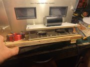
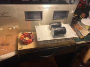
Almost back together. Passes bench tests, idled for half hour or so then set bias to 350mV. Going to close things up and give a listen but I have to inspect a crossover in my right side 3 way cabinet first. Something wonky and it’s remains in the right cabinet after swapping amps, pre amps, signal paths left to right and even swapped the drivers left to right. The passive crossover is all that remains common to this problem...
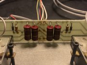
Just looking at how to remove the one from the light board. If I remove the two 10 ohm resistors and the cap, the signal path through the meters will be open...You have too many Zoebels Andrew...
Just looking at how to remove the one from the light board. If I remove the two 10 ohm resistors and the cap, the signal path through the meters will be open...
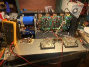
Bias? Base on the + rail to the speaker output no? That’s the collector bus bar on the negative side? I get the same reading across the bias resistor or the test points on the board? Am I making a big dummy move here? (Wouldn’t be the first time...)Also trying to figure out what you are measuring with your DMM?
There is a yellow test point for that on the upper edge of the control board. You are reading 0.002V of bias.Bias? Base on the + rail to the speaker output no? That’s the collector bus bar on the negative side? I get the same reading across the bias resistor or the test points on the board? Am I making a big dummy move here? (Wouldn’t be the first time...)
Oh fug, the amp is off in that pic Joe. Want me to test again on? When using the test point, I don’t check to ground do I? Was 350mV both channels. Also, I just removed the caps from the light board.There is a yellow test point for that on the upper edge of the control board. You are reading 0.002V of bias.
If your output offset is zero, which it is if the amp is working properly, you use the black ground test point on the top edge of the board for your negative DMM lead and the yellow bias test point for your positive DMM lead.Oh fug, the amp is off in that pic Joe. Want me to test again on? When using the test point, I don’t check to ground do I? Was 350mV both channels. Also, I just removed the caps from the light board.
Damn, forklift being dropped off for repair. BRB.
so that there is less chance of making a bad move with your test clips and accidentally blowing something up.Oh fug, the amp is off in that pic Joe. Want me to test again on? When using the test point, I don’t check to ground do I? Was 350mV both channels. Also, I just removed the caps from the light board.
Damn, forklift being dropped off for repair. BRB.