AngrySailor
Veteran and General Yakker
- Joined
- Oct 15, 2014
- Messages
- 3,419
- Tagline
- ---not quite right
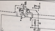
This mess can’t be PL

I think that wouldYep, sure looks like that is what they were doing. One set straight to the board and the other set from the jacks to pots to board.. It's been a few years since I had a Series 1 apart... bear with me bud.
You can do this with one set of jacks and the switch. remove the direct set..
Ok that’s pretty much what I figured, just didn’t want to make a big oopsie. Going with one set of RCA’s makes the switch and cap functional and ditches 12” ofNot needed with the WO board, just the input from the pots, inputs through the Direct/normal switch with one way through the cap, other withouit the cap. You should be able to wire the switch the same way I did on the pic i linked...
No problem Lee, you guys been Über helpful and patientYes, there are and I apologize for not keeping up there Andrew..
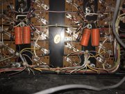
This amp has been molested some but I checked out the output sockets today, cleaned a bit of white goo in the house but spent some time innashop packing up other long term projects to reclaim some bench space. I’ll take Tim out tomorrow and hit him up with some harsher cleaner and compressed air for a final clean. Not one broken TO3 socket, found one bad connection at the power switch/light junction and one wire with bad insulation to a thermal switch that needs to be changed. Otherwise looks ok. Should I take the 4x 4uf caps out of circuit on the back plane and test them while im here? Anything else before installing the board and starting bring up?
Ok we just wondering if I should test em while they’re easy to get. I get that caps sometimes aren’t critical as is “YOU GOTTA RE-CAP!” But them old looking paper caps I figured be worth a test if needed whileYeah. They can stay for now
..
")
I’m confused about the PL drawing and the level pots. Looks like direct bypasses the pots but I haven’t ohmed it out yet (my bad)