
You are using an out of date browser. It may not display this or other websites correctly.
You should upgrade or use an alternative browser.
You should upgrade or use an alternative browser.
700/1 “Tim” WOPL driver board
- Thread starter AngrySailor
- Start date
AngrySailor
Veteran and General Yakker
- Joined
- Oct 15, 2014
- Messages
- 3,419
- Tagline
- ---not quite right
Went to bed early yesterday, woke up wide awake, figure out a few hours in on Tim before regular day stuff opens up. Got one more spurt of sand blasting on the old tractor then I can finally pack up the blaster and be done with that mess... guess I’ll put the power supply together this morning.
AngrySailor
Veteran and General Yakker
- Joined
- Oct 15, 2014
- Messages
- 3,419
- Tagline
- ---not quite right
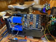
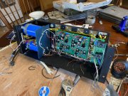
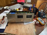
Power supply almost done, just gotta add the snubber caps. Replaced the old wires to the caps. They were borderline short and the insulation was melted from several rectifier changes. Getting closer, looking forward to bringing it up!
once it’s working I can send the big Carver to 18” sub duty and let Tim rock the 4x15 three ways...
once it’s working I can send the big Carver to 18” sub duty and let Tim rock the 4x15 three ways...
Attachments
AngrySailor
Veteran and General Yakker
- Joined
- Oct 15, 2014
- Messages
- 3,419
- Tagline
- ---not quite right
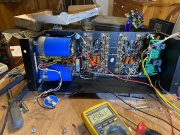
Snubber caps all soldered in. 206vDC out of the rectifier. Large filter caps not in circuit yet, no need to charge those bad boys yet. What do I need for a resistor to safely discharge them btw. If I recall they are also formed already right? The amp will be brought up on a variac and DBT anyways so probably doesn’t matter either way...
Attachments
AngrySailor
Veteran and General Yakker
- Joined
- Oct 15, 2014
- Messages
- 3,419
- Tagline
- ---not quite right
AngrySailor
Veteran and General Yakker
- Joined
- Oct 15, 2014
- Messages
- 3,419
- Tagline
- ---not quite right
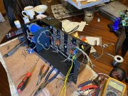
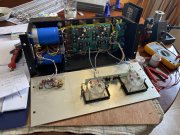
Ok, DCP AC connections made, with the 4 snubber caps that’s a lot of wires on each terminal of the rectifier. Gonna consider this amp a learning experience as it’s my first one, I would do things a little different next time for sure... Linda will be much “prettier”...
So this DCP wiring, there are three ground terminals, left, right speaker (this is a single wire on the 700/1) and the ground terminal to the bus bar. Is not the speaker ground direct to the bus? Won’t a second wire there be redundant? I’m thinking to break the speaker negative out into two wires, then there’s there’s the light/meter board grounds and the driver board ground attached to the speaker negative leads. Tie them to either ground? Can’t see it making a difference? Also it’s been a while since I pulled this apart, the meters connect to the speaker + right?
So this DCP wiring, there are three ground terminals, left, right speaker (this is a single wire on the 700/1) and the ground terminal to the bus bar. Is not the speaker ground direct to the bus? Won’t a second wire there be redundant? I’m thinking to break the speaker negative out into two wires, then there’s there’s the light/meter board grounds and the driver board ground attached to the speaker negative leads. Tie them to either ground? Can’t see it making a difference? Also it’s been a while since I pulled this apart, the meters connect to the speaker + right?
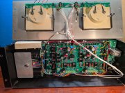
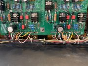
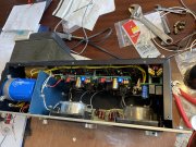
On a full WOPL, 2 speaker ground wires run from the DCP to the buss bar. In the photo, these are the two white wires that come off the DCP and go down. The red wire on the DCP goes to the rectifier, the black to the buss bar. The yellow wires you see at the DCP are the + outputs coming off the backplanes, right and left channels.
The light bar pcb is powered by wiring that's incorporated into the transformer, should be a loose pigtail coming off the transformer. The meter signals come off the backplane in a WOPL, not sure about original wiring, probably off the backplane. Additionally there is one extra voltage wire going to the DCP that is green in the photo, think this is B+, but I'm on the road, on cell, can't check.
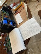
Good thing is you have a original 400 to look at that should help at this stage. Hope this photo helps even if it is a 400. Hi Res, should be able to zoom in, the light bar wiring should be clear along with the DCP grounding.
The light bar pcb is powered by wiring that's incorporated into the transformer, should be a loose pigtail coming off the transformer. The meter signals come off the backplane in a WOPL, not sure about original wiring, probably off the backplane. Additionally there is one extra voltage wire going to the DCP that is green in the photo, think this is B+, but I'm on the road, on cell, can't check.
Good thing is you have a original 400 to look at that should help at this stage. Hope this photo helps even if it is a 400. Hi Res, should be able to zoom in, the light bar wiring should be clear along with the DCP grounding.
Attachments
Last edited:
AngrySailor
Veteran and General Yakker
- Joined
- Oct 15, 2014
- Messages
- 3,419
- Tagline
- ---not quite right
Oh, Andrew, all these somewhat "extra" ground wires are there for a reason. Don't want to mix power supply ground wires with audio ground wires. That's why the DCP power supply wires run across the top of the chassis and the speaker ground wires run across the bottom. Why two speaker ground wires? Trying to maintain maximum channel seperation. Think dual mono block amplifiers in one package.
AngrySailor
Veteran and General Yakker
- Joined
- Oct 15, 2014
- Messages
- 3,419
- Tagline
- ---not quite right
Yeah I can run an extra speaker ground easy enough. I did run the AC supply across the top away from signal wires though. Just sitting down and identifying all the driver board connections now. Make up a list by color so it’s easy to follow when I start soldering.
AngrySailor
Veteran and General Yakker
- Joined
- Oct 15, 2014
- Messages
- 3,419
- Tagline
- ---not quite right
Ok I’m sorting out the board connections now. Just wanted to check a couple things. This is a quasi build. On the left channel there is B+ & B- but not on the right channel. There is also a connection the the bulk cap bus on the right channel only. These connections are taken care of in the board correct? I think I have everything all pinned out. If this is the case.
Attachments
AngrySailor
Veteran and General Yakker
- Joined
- Oct 15, 2014
- Messages
- 3,419
- Tagline
- ---not quite right
Haha this 700/1 seems to have some significant differences compared to the later 700’s...
AngrySailor
Veteran and General Yakker
- Joined
- Oct 15, 2014
- Messages
- 3,419
- Tagline
- ---not quite right
AngrySailor
Veteran and General Yakker
- Joined
- Oct 15, 2014
- Messages
- 3,419
- Tagline
- ---not quite right
AngrySailor
Veteran and General Yakker
- Joined
- Oct 15, 2014
- Messages
- 3,419
- Tagline
- ---not quite right
AngrySailor
Veteran and General Yakker
- Joined
- Oct 15, 2014
- Messages
- 3,419
- Tagline
- ---not quite right

AngrySailor
Veteran and General Yakker
- Joined
- Oct 15, 2014
- Messages
- 3,419
- Tagline
- ---not quite right
Got bigger problems seems...And remember, your charging those caps, don't drop any output transistors in with them charged. Need to discharge them first.