- Joined
- Jan 14, 2011
- Messages
- 75,905
- Location
- Gillette, Wyo.
- Tagline
- Halfbiass...Electron Herder and Backass Woof
Looking real good Andrew!

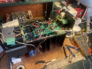
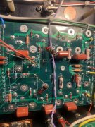
I did move the rectifier as you say, the one meter terminal was still VERY close to the plate (maybe 1/32”) so I just made a little extra room. I blew up one 400/1 meter already doing something stupid and took probably ten years to find another (thanks Lee).Too late now Andrew but you could have avoided the milling of your hold down plate by mounting the bridge in the recommended rear hole (as pictured on the web page), not the front hole. When mounted in this position, the edge of the hold down plate almost comes in contact with the chassis side wall.
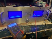
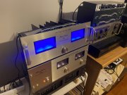
They don’t photo well at all. Look much better in person...Andrew, those blue LEDs, in the photos are throwing beams of light like laser pointers.
Good to see you back, and Linda up and running.
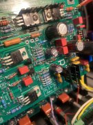
Thanks Lee. I’ve actually enjoyed fucking up as It forces me to learn much more about the driver board. Couple questions... r9&10 1 ohm resistor on the back plane, it was in Kohm range so I bridged a 10 ohm across. Replaced blown emitter resistors on xq 5&6 with original pl400 emitter resistors. Only xq 5&6 are populated rn.Good job getting it squared away..
Lots of help available here...Good job getting it squared away..
R9 and 10 will work as 10 ohms temporarily however should be 1 ohm after you get things squared awayThanks Lee. I’ve actually enjoyed fucking up as It forces me to learn much more about the driver board. Couple questions... r9&10 1 ohm resistor on the back plane, it was in Kohm range so I bridged a 10 ohm across. Replaced blown emitter resistors on xq 5&6 with original pl400 emitter resistors. Only xq 5&6 are populated rn.
can I use the .22 ohm PL emitter resistors for now and are the 1ohm r9&10 only used as a bridge/jumper? What is acceptable there until proper parts are here?
thanks all
Thanks Joe, I’ll be ordering stuff for a 700b soon, your kits for Tim and Linda had a few extra goodies that really helped. Couple extra diodes and resistors but man, did I ever blow this up...R9 and 10 will work as 10 ohms temporarily however should be 1 ohm after you get things squared away