400/1 “Linda” Full WOPL

AngrySailor

Veteran and General Yakker
Joined
Oct 15, 2014
Messages
3,419
Tagline
---not quite right
#82
Too late now Andrew but you could have avoided the milling of your hold down plate by mounting the bridge in the recommended rear hole (as pictured on the web page), not the front hole. When mounted in this position, the edge of the hold down plate almost comes in contact with the chassis side wall.
I did move the rectifier as you say, the one meter terminal was still VERY close to the plate (maybe 1/32”) so I just made a little extra room. I blew up one 400/1 meter already doing something stupid and took probably ten years to find another (thanks Lee).
 

AngrySailor

Veteran and General Yakker
Joined
Oct 15, 2014
Messages
3,419
Tagline
---not quite right
#83
I should have measured while it was apart but what are the two meter ranges available by jumper and which position is which? Can’t find my original documents for the light board. I cranked it up a bit and hardly got the meters moving before my left channel (probably speaker issue) shut me down. Which position is which? Jumper on top or bottom for respective sensitivity? Have to fix a frozen pipe at a friends rn or I’d be diagnosing things...
 

AngrySailor

Veteran and General Yakker
Joined
Oct 15, 2014
Messages
3,419
Tagline
---not quite right
#85
Had a bad compression driver in the left cabinet. Was working but half melted VC and tone was way off. Speakers sound correct now, think I have issues with other components in the signal path. Did some signal generator testing. I’m going to do that again and write out the results to post later. The amp seems perfect though, there’s an imbalance somewhere before the amp...
 

mr_rye89

Veteran and General Yakker
Joined
Aug 12, 2015
Messages
2,685
Location
Land of Entrapment
Tagline
Lost in the Ozone Again
#87
Yep. Pictures (taken with the Iphone 12 pro) of my meters look pee yellow, but they look incandescent in real life. Pictures taken with my Nikon D700 look more real to life. Phone cameras are still ass, still BTFO by a 15 year old DSLR.
 

AngrySailor

Veteran and General Yakker
Joined
Oct 15, 2014
Messages
3,419
Tagline
---not quite right
#88
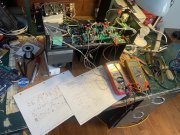
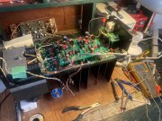
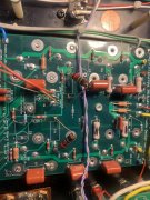
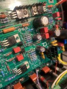
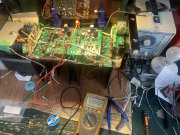
I was waiting to post until I got things figured out but I blew Linda’s right channel up doing some testing... drove the channel to near clipping and was taking some voltage readings in and out as I have an imbalance somewhere in my system and wanted to eliminate any possibility of the amplifier. Anyways I blasted the input voltage a little high by accident and clipped her real bad, blew the b- rail fuse... then of course being lazy, instead of bringing the dim bulb over to the amp, I slammed a new fuse in and let ALL the smoke out of the right channel... 4 blown output transistors, emitter resistors, bias resistor, r9&10 on the back plane r28 and a couple diodes in the limiter circuit on the driver board... Fug... It seemed the problem was with the driver board as bias was low but this ended up being related to the backplane. She’s back testing good now with drivers and one row of outputs installed. I’ve just tagged some components onto the backplane and driver board for testing, now that things are checking good I’ll start reworking the boards.

Have at me fellas, I’m a dumb ass!
 

Attachments

AngrySailor

Veteran and General Yakker
Joined
Oct 15, 2014
Messages
3,419
Tagline
---not quite right
#90
Geez, when I edit that post I changed a couple sentences around and forgot to mention Grapplesaw, he was a HUGE help with the diagnostics and repair. Sorry you got lost out of the original post!
 

AngrySailor

Veteran and General Yakker
Joined
Oct 15, 2014
Messages
3,419
Tagline
---not quite right
#93
Good job getting it squared away..
Thanks Lee. I’ve actually enjoyed fucking up as It forces me to learn much more about the driver board. Couple questions... r9&10 1 ohm resistor on the back plane, it was in Kohm range so I bridged a 10 ohm across. Replaced blown emitter resistors on xq 5&6 with original pl400 emitter resistors. Only xq 5&6 are populated rn.

can I use the .22 ohm PL emitter resistors for now and are the 1ohm r9&10 only used as a bridge/jumper? What is acceptable there until proper parts are here?

thanks all
 

Gepetto

Administrator
Staff member
Joined
May 15, 2011
Messages
14,065
Location
Sterling, MA
Tagline
Old 'Arn Enthusiast
#95
Thanks Lee. I’ve actually enjoyed fucking up as It forces me to learn much more about the driver board. Couple questions... r9&10 1 ohm resistor on the back plane, it was in Kohm range so I bridged a 10 ohm across. Replaced blown emitter resistors on xq 5&6 with original pl400 emitter resistors. Only xq 5&6 are populated rn.

can I use the .22 ohm PL emitter resistors for now and are the 1ohm r9&10 only used as a bridge/jumper? What is acceptable there until proper parts are here?

thanks all
R9 and 10 will work as 10 ohms temporarily however should be 1 ohm after you get things squared away
 

AngrySailor

Veteran and General Yakker
Joined
Oct 15, 2014
Messages
3,419
Tagline
---not quite right
#96
R9 and 10 will work as 10 ohms temporarily however should be 1 ohm after you get things squared away
Thanks Joe, I’ll be ordering stuff for a 700b soon, your kits for Tim and Linda had a few extra goodies that really helped. Couple extra diodes and resistors but man, did I ever blow this up...:oops:
 

AngrySailor

Veteran and General Yakker
Joined
Oct 15, 2014
Messages
3,419
Tagline
---not quite right
#98
Looking at swapping crossovers with pops... his is stereo 3 way which will allow me to use both Tim and Linda along with the monster carver. Hoping to get Linda patched up tonight enough to test drive then I’ll have to modify the speaker jacks on the three way cabinets to separate the 15’s from the passive crossover which will only be used for the mid/horn split.
 
Top