Greg
Journeyman
- Joined
- Jun 11, 2022
- Messages
- 204
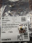
Would this be suitable replacement Pot for main volume pots on PL700 ii Diagrams mention 100 K ?
PDA241-HRT02-104B0 Bourns | Mouser
PDA241-HRT02-104B0 Bourns | Mouser

Not if you want to use the original "D" shaft knobs. Filing/grinding the shaft is a laborious poor solution. Been there.Would this be suitable replacement Pot for main volume pots on PL700 ii Diagrams mention 100 K ?
PDA241-HRT02-104B0 Bourns | Mouser
Not if you want to use the original "D" shaft knobs. Filing/grinding the shaft is a laborious poor solution. Been there.
Hmm Alternatives ?Not if you want to use the original "D" shaft knobs. Filing/grinding the shaft is a laborious poor solution. Been there.
Buy new knobs...Hmm Alternatives ?
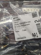
I originally used these 100k.
Then went to 50k to match the input impedance of all WOPLs to the original 50k attenuators I kept in the 700 Pro.
I use solid shafts and these set screw knobs, but it isn't to difficult to Dremel a solid shaft to a "D" shaft.
https://www.tubesandmore.com/products/knob-aluminum-set-screw-notched-tip-125-diameter
George when did we move from 100k to 50k pots. I’ve not seen any documents for that change. Please guide meI originally used these 100k.
Then went to 50k to match the input impedance of all WOPLs to the original 50k attenuators I kept in the 700 Pro.
I use solid shafts and these set screw knobs, but it isn't to difficult to Dremel a solid shaft to a "D" shaft.
https://www.tubesandmore.com/products/knob-aluminum-set-screw-notched-tip-125-diameter
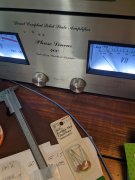
Glenn, the 700 Pro were built with very nice Alps 50K attenuators that easily come apart for cleaning and greasing. I wanted to keep those. Because I'm using it biamped, I wanted to match that input impedance on the other amps.George when did we move from 100k to 50k pots. I’ve not seen any documents for that change. Please guide me
Glenn, the 700 Pro were built with very nice Alps 50K attenuators that easily come apart for cleaning and greasing. I wanted to keep those. Because I'm using it biamped, I wanted to match that input impedance on the other amps.
I have yet to really understand input impedance. I've read about how to check it, and Joe has commented on it and how PL used a high input impedance probably because people were using tube preamps. My understanding which may be faulty, is that total resistance of the attenuator pot affects input impedance. Hopefully Joe will comment on this.
No, because channel 1 has 100K in parallel with the 49K input impedance on the control board and channel 2 has 50K in parallel with the 49K input impedance. With a low output impedance preamp of say, 100 ohms, you will not notice a difference but with a tube preamp with 50K output impedance, you will need to turn the preamp up much higher to offset the extra loading.Joe,.So, let's say I have a 100K on one channel, and a 50K on the other and both are wired correctly and "turned to the right" for lowest resistance and highest amp output.
Are they electrically equivalent to each other at that position? Seems like they should be, but reading about input impedance awhile back made me question that assumption. Thanks.