Rega Planar 3 Upgrade(?) path

J!m

Veteran and General Yakker
Joined
Dec 24, 2019
Messages
10,960
Location
Connecticut
Tagline
BOT
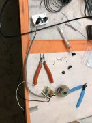
More fiddly work. Attached wires to the fuse holder and attached the connector to the motor board. Slow progress.

I stopped by the local store and got some flag connectors to run wires off the inlet filter at 90 degrees. That’ll be sorted tomorrow. If I’m clever, I’ll be able to remove the motor, board and harness as an assembly for service too.
BE46D624-5D5A-4E55-88D3-BE166B859336.jpeg BD14C634-DCD7-41C9-9A3C-CE47280FB22C.jpeg F1F6696B-28D8-46B0-8B98-6571E92ACB3B.jpeg
 

J!m

Veteran and General Yakker
Joined
Dec 24, 2019
Messages
10,960
Location
Connecticut
Tagline
BOT
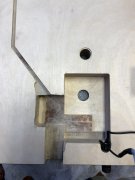
Started on wiring and realized I would not be able to adjust the motor very much. It shouldn’t need much honestly, but I may go with longer belts and get crazy..,

So, I had to create a new space for the motor board. Had I realized this earlier, I might have mounted the fuse on the other side if the power inlet. But it’s fine.

93F4F44B-3B6E-4BE0-A223-D0CE4415E171.jpeg 2A25B22A-2DBE-4950-A000-AB01493CC383.jpeg 9DACF953-A613-4D18-9B92-38B2E0C4A570.jpeg

That “brown” area in the large cavity is a raised area that was under the board. I took it out so the entire large cavity is open and flat.

The cable to the switch and LED is now shorter, so I need to deal with that, but pretty smooth all things considered.
 

George S.

Veteran and General Yakker
Joined
Feb 18, 2020
Messages
5,036
I watch those YouTube videos of those pro wood worker guys building massive plinths out of exotic woods. They're all using jigs and patterns to recreate a plinth that they've built before, perhaps many times.
I've often thought about doing the same, and come to the conclusion that I'd have to build at least 2 or 3 to get the jigs and patterns correct.
Looking at what your doing basically"freehand" and figuring out the cuts and recesses as you go is impressive. Good job!
 

J!m

Veteran and General Yakker
Joined
Dec 24, 2019
Messages
10,960
Location
Connecticut
Tagline
BOT
I (and you) can make temporary jigs. I actually have a book in making jigs and fixtures for woodworking. It was a big help for designing the method for a 15 degree scarf joint to attach the headstock to the neck…

But if you have a shallow pattern but (mine is 1” but I used to have an arsenal of router bits back in the day…) and then you use plywood to define straight lines and hard stops. For this work, it is not seen, so I just go for it.

To do the counterbores, I put the wrong size bearing on the bottom bearing bit, so it cuts deeper than the bearing…
 

J!m

Veteran and General Yakker
Joined
Dec 24, 2019
Messages
10,960
Location
Connecticut
Tagline
BOT
More boring stuff today.

Made the bing for the VTA disc template. I’m going to run around the outside, using the bore for the tone arm to keep it well centered.

It will be “D” shaped- flat at the edge where the wheel protrudes. Still on the fence but the plan at the moment is to have the edge peek out through the wood plinth.

Then I polished the main shaft of the sub platter. Finish was worse than the stock Rega; now it’s better. I can do less than one micron but I couldn’t find the Diamond suspension. This was done with 10 micron paper and thread cutting oil.
6B050048-D6DD-4F83-A1FA-30D40EEC4F00.jpeg F57D69C5-7FDE-4036-A87F-DD4C2A452646.jpeg CD8C9535-ED4C-4A0B-A473-67CC73C68C17.jpeg B46BE6FF-B23D-4588-B464-A6B9625A4383.jpeg 651DF185-2FD9-4209-9E95-2BD51B6DF0F4.jpeg B1E3444E-0D47-400D-8983-4566F083C789.jpeg
 

J!m

Veteran and General Yakker
Joined
Dec 24, 2019
Messages
10,960
Location
Connecticut
Tagline
BOT
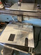
More boring stuff but I did hear back from the machine shop (hopefully have the last quotes soon) and the rubber place. If I go “big” we’ll make a die to stamp out the rubber sheet. Since it’s just one for now, it’ll be water-jet cut. Hopefully I have that quote tomorrow as well.

Otherwise I just cut the ears off the motor. I need to cut the wire channel a bit deeper and of course re attach another broken wire.
BE427A91-DF69-4352-ACBB-BDAD6F34604D.jpeg
 

J!m

Veteran and General Yakker
Joined
Dec 24, 2019
Messages
10,960
Location
Connecticut
Tagline
BOT
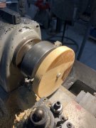
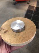
I needed a break from micro-machine design...

Back on this. Machine shop is swamped so I still don't have my quotes. But, it gives me more time to save money to pay them...

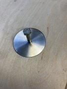
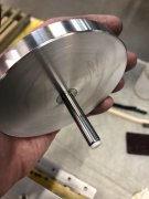
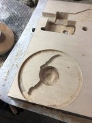
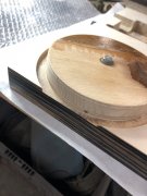
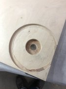
I needed a way to accurately rout for the VTA lock disc. Similar to the Michell "Finger Nut".

Anyway, this locates in the counterbore for the tonearm, and I will rout around the outside of it, to create a circle of appropriate diameter, on center, and of proper depth. The edge of the disc will peek out the side of the plinth, just above the sub-plinth, for loosening and tightening. Not quite VTA on the fly, but at least you don't have to reach under the table, or prop it up on blocks, while fine-tuning... I will have a "wall" thickness of 0.165" on the back of the plinth, but it should be enough in Birch ply. I'll reinforce it with cyanoacrylate in that area, after I'm done with the routing.

IMG_4583.JPG IMG_4584.JPG IMG_4585.JPG IMG_4586.JPG
 

J!m

Veteran and General Yakker
Joined
Dec 24, 2019
Messages
10,960
Location
Connecticut
Tagline
BOT
Got the counterbore done for the arm nut today. (Also got the quote for the water jet cut rubber sheet)

61707BC4-D075-4685-A6FD-FE71EF3AC145.jpeg 2DC8CFC8-49B6-400A-A4EC-97FE898C0860.jpeg E26A2E57-57F5-4FEC-9744-229226970EC3.jpeg

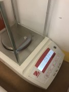
I also made a heavier anti-skate weight for the Kenwood. This is why I was hearing distortion on inner grooves…

9B0B39A7-4912-443E-A28C-B1B248C1C5A1.jpeg 8A7C69E4-84AF-4716-BE03-C29204287531.jpeg AAB77A14-B9B6-46AC-BB66-D472776B57F4.jpeg

I needed to add a penny (3g) to the 1g weight all the way at the end of the arm, to get it to run clean. The new weight is 5g so I can run it more in the middle of the adjustment range.
 
Top