Lewcifer
New Around These Parts
Ugh, thanks for your patience.
Okay, at those resistors, I'm seeing 507mv on the first one and 476mv on the third one.After hooking your meter to the bias resistor, turn the amp on and see what it is. Offset has to be checked with amp on..
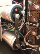
Just a couple questions to clarify because I want to do this safely and not get my 1980s hairstyle back.Ok....have you checked rail voltages yet? Minus lead on the bus between the caps, positive on the plus and then minus cap terminals...should be about 80 volts DC..

MVThe 16.5 reading ....is that volts or Mv?
Thanks! I’m getting about 78V on both.Ok, the copper bus bar is the ground. The other terminal of each cap is your plus and minus rail voltage , should have plus and minus 80 vdc...
Oh, yes! about 78 on the upper one and -78 on the lower one.Your getting a minus on the bottom cap aren't you?? The one with the green wire?
Yeah, it does click every time I plug it in.Well nothing terrible is wrong, are you getting a relay click on the DCP on power up?
I did print out a service manual today. I will look into it. Thank you SO much.Ok, that's a good sign. Have you read up on adjusting bias? That's next, bring bias down to 375 mv.....
Seems like I should invest in some alligator clips before proceeding. Or I might be able to borrow some from the mechanic at work.Hook your meter to the first row 10 ohm bias resistor, turn amp on and adjust thumbwheel pot while observing reading. With those old open pots it can get real erratic..
