HELP! PL400 crackling/static

Lewcifer

New Around These Parts
Joined
May 24, 2020
Messages
35
Location
Pacific northwest
#1
First, hello! I'm new here. This is my first post and first attempt at DIY electronics, so please be gentle. I'm a middle-aged guy in Oregon. I press records for a living.

About a month ago, I got a PL400 for well below the prices I see on Ebay. I gave it a quick audition in the thrift shop just to make sure it lights up, the meters move, and sound comes out.

I added the DC relay from Don Imlay and a White Oak meter board before hooking it up at home with my Marantz 2238B and Bose 901/II's (I know... *ducks*)

Now I have it hooked up, and it works and sounds fine, except that I'm getting occasional bursts of static, I think just from one side. Sometimes it's mild, sometimes it's LOUD and trips the relay. Or at least I think that's what is happening. The lights stay on, but no output. turning it off and back on restores output.
Volume level doesn't seem to make a difference. Today I got through an entire side of an album with no problem, then after a few minutes of the needle just playing in the matrix, there was a huge blast of static and the amp shut down.
The first time it happened, I took the needle off the record and turned the volume all the way down, and with no input, the meters spent about a minute sweeping wildly from side to side with enough force that I could *hear* them hitting the end of their range "tink, tink, tink", YIKES.

So what am I dealing with here?
Is it possible I made a bad connection installing the DC relay?
Maybe an issue with the Marantz pre-out?
Bad output transistors in the PL400? (please say no)
Something else?
PLEASE HELP.

A little more info that may or may not be relevant:
-This seems to be an early PL400 (4 fins, serial #2412).
-Amp looked to be untouched and in great shape when I opened it up (minimal dust, no visible heat damage).
-I did build a DBT when I added the new boards and it passed the test just fine.
-It's my first project, but I did a ton of homework (reading and re-reading instructions for the two boards I put in,
watching install videos, watching soldering videos, bought a new soldering station, etc), so I'm pretty sure I did a decent job.
-I've been using this Marantz/901 combo for years with no issue, but I've never used the pre-out jacks.
-I have 2A fuses inline between the PL and the speakers.
-I still have another pair of little speakers hooked directly to the "system 2" output on the Marantz.
-I don't own any testing equipment besides the dim bulb and a cheap DVM.

Any suggestions appreciated!
 
Last edited:

K-5BLAZER

Journeyman
Joined
Feb 18, 2017
Messages
404
Location
las cruces nm
Tagline
square body cause I dint want a plastic 4x4
#2
first welcome Don Imlay is a member here user name wattsabunbant also Joe from white oak is a member here user name gepetto. as one of our member would tell you in stock form even with the dcp board these amps are ticking time bombs. some one that knows a lot more then I do will chime in I was told by the same member that if you start a wopl convertion it is best to do it all at once so your new parts do not get taken out with all the bad old ones. I leave you with... TIC TIC TIC...
index.jpg e886c872dc82e1b10032968c3f667ac9.jpg index.jpg aaah-theres-the-kaboom-quickmeme-com-aaah-theres-the-kaboom-50344989.png
 
Last edited:

laatsch55

Administrator,
Staff member
Joined
Jan 14, 2011
Messages
74,939
Location
Gillette, Wyo.
Tagline
Halfbiass...Electron Herder and Backass Woof
#7
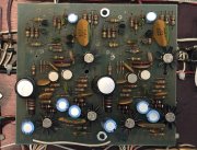
Ok...you have a PL 14 driver board. Good job on the fuses. Gotta work in the morning, going to bed..
 

mlucitt

Veteran and General Yakker
Joined
Jun 24, 2011
Messages
3,497
Location
Jacksonville, FL
#8
The fact that you mentioned "meters" (I am assuming both meters) were swinging to full scale (common to both channels), and you had near normal music from both channels occasionally when turning off and back on, (no permanent damage to the Control Board), and the lights stayed on (good transformer). I am guessing you have a problem in one or both of the bulk capacitors.
Joe offers these capacitors as a replacement/upgrade for $63.00 and they are one of the first changes I make to any PL amplifier. You see, the bulk capacitors have a certain lifespan, anywhere from 15-20 years. Yours are at least 43 years old, maybe 48. Even if the amplifier has not been used, the dielectric in those large capacitors has dried out or become unstable, take your pick. Replace them and have another go.
 

gtv2000

New Around These Parts
Joined
Jul 23, 2019
Messages
23
Location
Co Springs
#9
I had a similar issue with my 400. I replaced the input transistors on the control board and it went away, but I didn't use it for very long like that (maybe a month) before I got the White Oak driver board installed.
 

Lewcifer

New Around These Parts
Joined
May 24, 2020
Messages
35
Location
Pacific northwest
#10
The fact that you mentioned "meters" (I am assuming both meters) were swinging to full scale (common to both channels), and you had near normal music from both channels occasionally when turning off and back on, (no permanent damage to the Control Board), and the lights stayed on (good transformer). I am guessing you have a problem in one or both of the bulk capacitors.
Joe offers these capacitors as a replacement/upgrade for $63.00 and they are one of the first changes I make to any PL amplifier. You see, the bulk capacitors have a certain lifespan, anywhere from 15-20 years. Yours are at least 43 years old, maybe 48. Even if the amplifier has not been used, the dielectric in those large capacitors has dried out or become unstable, take your pick. Replace them and have another go.
Thanks for the response! Yes, it was both meters sweeping wildly side to side, but moving independently of one another. Again, this was with the preamp turned all the way down and no music playing.
I had looked into the capacitor upgrade, and it seems like an easy swap, but I just wanted to try this thing out first and see if I could maybe wait a bit to do the upgrade. Looks like maybe I need to move that project to the front burner.
 

MarkWComer

Veteran and General Yakker
Joined
Nov 1, 2014
Messages
3,513
Location
Gaston, SC
Tagline
Victim of the record bug since age five
#11
You might want to do a diode check on your output transistors, check the emitter resistors, too.
Check for conductance with your DVM against collector to base, collector to emitter, and emitter to base on the output transistors. The emitter resistors are .22Ω, will be difficult for your DVM to measure something that low, but if they’re obviously burned or cracked, they’re bad. If the transistor is bad, assume it took the resistor with it.

Just another thing to check...
 

Lewcifer

New Around These Parts
Joined
May 24, 2020
Messages
35
Location
Pacific northwest
#15
Check offset and bias before going any further. Do you have a service manual??
I did check offset after putting in the DC relay and got .1mv on one side and zero on the other. Maybe I should check again? I'm not sure how to check bias (maybe someone here can walk me through it?). I do have the service manual downloaded. I just haven't got it printed out yet. Just now I was skimming through it and saw that replacing Q1 & Q2 is the recommended fix for excessive offset. Does that sound right?
 

laatsch55

Administrator,
Staff member
Joined
Jan 14, 2011
Messages
74,939
Location
Gillette, Wyo.
Tagline
Halfbiass...Electron Herder and Backass Woof
#16
Yep, replacing Q1,Q2 will fix excessive DC offset if that's where it's coming from in the first place.

To check bias, locate the 10 ohm resistor on the backwall, there are 4 of them ,one each on each vertical row of out puts. We are concerned with the row closest to the transformer and the 3rd row from the transformer. Measure MV accross that 10 ohm resistor..
 

Lewcifer

New Around These Parts
Joined
May 24, 2020
Messages
35
Location
Pacific northwest
#17
Yep, replacing Q1,Q2 will fix excessive DC offset if that's where it's coming from in the first place.

To check bias, locate the 10 ohm resistor on the backwall, there are 4 of them ,one each on each vertical row of out puts. We are concerned with the row closest to the transformer and the 3rd row from the transformer. Measure MV accross that 10 ohm resistor..
Just checked offset again at the binding posts, and it's zero for both sides while the channel B meter is bashing around like a caged tiger.
should I be checking it where the output wires enter the relay, though?
Before I open it up to check bias, should this be done with any connections? power on? Power off?
I'm guessing I need to unplug it and let the caps discharge.
 

laatsch55

Administrator,
Staff member
Joined
Jan 14, 2011
Messages
74,939
Location
Gillette, Wyo.
Tagline
Halfbiass...Electron Herder and Backass Woof
#18
Yes, unplug and discharge caps, you don'yt want to slip the probe in there.

If you don't have a relay click the binding posts will show 0.000. Check where the wires enter the DCP board...
 

Lewcifer

New Around These Parts
Joined
May 24, 2020
Messages
35
Location
Pacific northwest
#19
Yep, replacing Q1,Q2 will fix excessive DC offset if that's where it's coming from in the first place.

To check bias, locate the 10 ohm resistor on the backwall, there are 4 of them ,one each on each vertical row of out puts. We are concerned with the row closest to the transformer and the 3rd row from the transformer. Measure MV accross that 10 ohm resistor..
I check this with the DCA section on my meter, correct? I'm seeing 0.00mv on both the first and third rows. Switching to ohms, they read 11.7 and 11.4
Checking offset where the output wires enter the relay (with the unit still unplugged) it's 25.6mv left and 24.3mv on the right.
 

laatsch55

Administrator,
Staff member
Joined
Jan 14, 2011
Messages
74,939
Location
Gillette, Wyo.
Tagline
Halfbiass...Electron Herder and Backass Woof
#20
After hooking your meter to the bias resistor, turn the amp on and see what it is. Offset has to be checked with amp on..
 
Top