WOPL Sniffer
Veteran and General Yakker
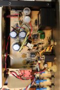
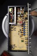
it looks like you have +unreg on one side of R1, and + reg out on the other side of R1 without R1 in the circuit. Can't work like that

Okay, I think I'm confused. Are you saying that, along with the leads from the new board, the R-1 & R-3 resistors should have remained in place?Yep, R1, and R3 need to be in the circuit, I believe it is hooked up wrong.
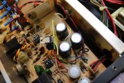
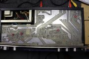
Okay, I'll go in now and pop that top so I can take a look.You gotta pop the top of your other preamp and look but I do believe your power switch is wired wrong. That would account for the button not working right. Sounds like a set of contacts are welded. 3 of the 4 contacts are soldered together. You can see that it's not right.
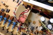
In comparing the two units, it looks as though all I have to do is cut the jumpers linking the front and back poles of the switch. Do you agree?are you using the skizmo or are you winging it?
In comparing the two units, it looks as though all I have to do is cut the jumpers linking the front and back poles of the switch. Do you agree?
One more time.NO that switch is now toast
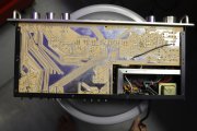
I'm not having any problems with images, and although 6 MB is a little large the detail is really nice. That being said you probably don't require more than 1100x tops.