- Joined
- Jan 14, 2011
- Messages
- 75,769
- Location
- Gillette, Wyo.
- Tagline
- Halfbiass...Electron Herder and Backass Woof
Happens to me too...


The BABB.....
No version of that in the 700 boards yet Dennis. Haven't talked to Joe about that possibility yet either. I really don't mind soldering the outputs in. Very little need anymore to change out a TO-3...
Good man..... Your Pats kicked some serious ass today...
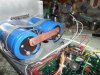
#14 to the B+,B- fuses from the caps, and #12 from the BR to the caps...
Got it in 1 D2!!!!!!!!!!!!!!!!!!!!!!!!!
Mo pics...
Hi
Just want to know how you configured the BR. It looks like You removed the stock cap and added four what 103k 400volt resistors?
What is the benefit fordowning this?
Thanks
minimum rating of 286.6v for 120VAC inputThe surge current increases with larger capacity capacitors and replacing the BR with a new one rated at 25 or 35 amps (@400 V or so) is commonly done. I think Lee is now using some 50 amp bridge rectifiers for the 700. Those aren't resistors - they're capacitors. If you replace the BR it is a good to add snubber caps across the four diodes. I believe that an optimal value for this is 0.022 uF and you'll want a rating of about 400 V or so. The value is not critical but you need to make sure the voltage rating is several hundred volts.
So Lee Have you Increaded all wire sizes by one size, is that correct?
What size for main supply line and power cord #14 ok?
minimum rating of 286.6v for 120VAC input
Are you fitting an australian power plug to it?
Whats the punch line D2???????? Seriously....George did send one. Funny lookin thing, has to be the one...ands yes I'll fit it..