I like the green illumination ring on the switch. It goes very well with the deep black anodized faceplate finish.I went with the non-illuminated version of that switch in the end, because I ended up backlighting the bullseye level as the power indicator.
I probably spent more by the time the dust settled…
You are using an out of date browser. It may not display this or other websites correctly.
You should upgrade or use an alternative browser.
You should upgrade or use an alternative browser.
White Oak Audio Design - Model ONE 1000 Watt Stereo Amplifier
- Thread starter mlucitt
- Start date
MarkWComer
Veteran and General Yakker
- Joined
- Nov 1, 2014
- Messages
- 3,520
- Location
- Gaston, SC
- Tagline
- Victim of the record bug since age five
“NO USER SERVICEABLE PARTS INSIDE”
Too funny!
Too funny!
Mohawk
Chief Journeyman
I like the green illumination ring on the switch. It goes very well with the deep black anodized faceplate finish.
I'm thinking deep blue lighted switch and back to the old school silver finish
- Joined
- Jan 14, 2011
- Messages
- 75,826
- Location
- Gillette, Wyo.
- Tagline
- Halfbiass...Electron Herder and Backass Woof
Fuckin Sexy Beast...
mlucitt
Veteran and General Yakker
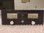
I assembled the Faceplate so that I could wrap it in bubble wrap and set it aside until I was ready for it. Note the rounded corners at the top.

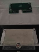
Between the VU Meter and the Circuit Board there is a "Light Guide" it has a smooth surface and a textured surface. The textured side goes toward the Circuit Board.

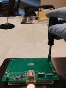
A 5/16" socket for the Meter Board Nuts. Not too tight here, just enough. Maybe a drop of Red Nail Polish on the threads.
The Meter is fully installed but not wired up yet.
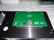
Those are some pretty meters, expensive too!

Installing the Power Switch (I went with Blue on this build), with a "No-Scratch" wrench.
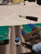
Meters wired up. I bent the Meter Terminals down to keep them out of harm's way.
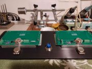
The Faceplate is assembled, except for the Meter Range Switch. I had one with a short toggle, but I ordered one with a longer toggle, the same switch as used on the Power Control Board. You will need a 1/2" Deep Socket to install the Attenuation Potentiometers, they are recessed. The knobs are as original to Phase Linear as I could find, they are RS Brand, P/N 499-961. You will need a 1.5mm Allen Wrench to tighten the setscrews.


Between the VU Meter and the Circuit Board there is a "Light Guide" it has a smooth surface and a textured surface. The textured side goes toward the Circuit Board.

A 5/16" socket for the Meter Board Nuts. Not too tight here, just enough. Maybe a drop of Red Nail Polish on the threads.

The Meter is fully installed but not wired up yet.

Those are some pretty meters, expensive too!

Installing the Power Switch (I went with Blue on this build), with a "No-Scratch" wrench.

Meters wired up. I bent the Meter Terminals down to keep them out of harm's way.

The Faceplate is assembled, except for the Meter Range Switch. I had one with a short toggle, but I ordered one with a longer toggle, the same switch as used on the Power Control Board. You will need a 1/2" Deep Socket to install the Attenuation Potentiometers, they are recessed. The knobs are as original to Phase Linear as I could find, they are RS Brand, P/N 499-961. You will need a 1.5mm Allen Wrench to tighten the setscrews.

- Joined
- Jan 14, 2011
- Messages
- 75,826
- Location
- Gillette, Wyo.
- Tagline
- Halfbiass...Electron Herder and Backass Woof
Do we really give a rats ass about the knob being original-like to a PL?
Also, I need some measurements when you are far enough along so I can get a cabbage case built. No way should those puppies be shipped in anything less. It will belong to the forum to be used by anybody shipping a Model 1....hell;, I'll get two built if we need to...
Also, I need some measurements when you are far enough along so I can get a cabbage case built. No way should those puppies be shipped in anything less. It will belong to the forum to be used by anybody shipping a Model 1....hell;, I'll get two built if we need to...
J!m
Veteran and General Yakker
We’ll need two.
If it’s worth doing, it’s worth over-doing.
If it’s worth doing, it’s worth over-doing.
- Joined
- Jan 14, 2011
- Messages
- 75,826
- Location
- Gillette, Wyo.
- Tagline
- Halfbiass...Electron Herder and Backass Woof
We’ll need two.
If it’s worth doing, it’s worth over-doing.
Absolutely....
- Joined
- Jan 14, 2011
- Messages
- 75,826
- Location
- Gillette, Wyo.
- Tagline
- Halfbiass...Electron Herder and Backass Woof
Love the chamfer on the inside of the meter cutouts...its the small things sometimes...
Pulpmillguy
Journeyman
Nice...VERY NICE
57 pounds, 26 kgWhats the weight of the Model One?
The only practical way to build one of these is to purchase a small roll around cart. Put a plywood deck on the top and cover it with that foam wrap to keep from damaging things. That way you can access any side of the amp during the build process and spin the cart around as needed. To build one of these on a static bench is not practical unless you are as big as Shaq.
You can see the red cart I purchased to do this project in the pictures I posted earlier.
Last edited:
Pulpmillguy
Journeyman
After wrestling with my 700 during the upgrade I can appreciate your comment about that BEAST...another 12 lb would really make a difference!57 pounds, 26 kg
The only practical way to build one of these is to purchase a small roll around cart. Put a plywood deck on the top and cover it with that foam wrap to keep from damaging things. That way you can access any side of the amp during the build process and spin the cart around as needed. To build one of these on a static bench is not practical unless you are as big as Shaq.
You can see the red cart I purchased to do this project in the pictures I posted earlier.
grapplesaw
Veteran and General Yakker
Awesome vintage aviation pictures in the background!Very similar in weight to the dual 500
Bring it on I can handle that
Lee there are some Pelican shipping cases
The 1640 and 1640 may be more than big enough
lots on eBay
I bought a 1620 which may work as well
View attachment 78712View attachment 78713View attachment 78714
NEMA rack mount hole locations. We all have seen poorly executed attempts to drill NEMA rack hole locations in Phase Linear faceplates. It breaks your heart when you see one of those hack jobs. Knowing that, these holes are instead professionally placed by design in the faceplate. Crown DC300 amps similarly provisioned these holes by design.Joe, why 2 sets of holes in the faceplate?
To accommodate both 4” and 5” handles?
Last edited:
Vynuladikt
Journeyman
- Joined
- May 4, 2016
- Messages
- 466
- Location
- Northeast Iowa
- Tagline
- Love great audio, beermaking and pyrotechnics
Beautiful amp!
With a support shelf underneath it...That's going to require a very robust rack to mount this beast.


