Perfect, thank you for the clarification and detailed assembly pictures.You don't need to, it is a ground loop shunt. That is its purpose...
You are using an out of date browser. It may not display this or other websites correctly.
You should upgrade or use an alternative browser.
You should upgrade or use an alternative browser.
White Oak Audio Design - Model ONE 1000 Watt Stereo Amplifier
- Thread starter mlucitt
- Start date
Given you're tying chassis to earth ground, I assume both power supply and signal grounds will be isolated from chassis in this design?
Single point ground using the isolated bolt on the side of the transformer shield?
Single point ground using the isolated bolt on the side of the transformer shield?
Chassis ground and DC ground are totally separated, throughout. The DC single point ground is this area of the terminal block.Given you're tying chassis to earth ground, I assume both power supply and signal grounds will be isolated from chassis in this design?
Single point ground using the isolated bolt on the side of the transformer shield?

The isolated bolt routes all the circulating currents from the rectifier to the bulk caps and back. You do not want to upset a quiet ground with all that high current charging current path. The output of that stud is transferred to this area of the terminal block via the 12AWG white wire on the lower right in the photo which only carries signal currents back to ground, not AC charging currents. Each amp board has an analog ground wire (SGND) and a power supply ground wire (DGND) back to this single point ground on the terminal block. These are the dual white wires on the upper and lower left soldered into the solder lugs.
A lot of thought went into optimizing the ground wiring structure in the amp to create a very quiet noise floor. The double white wire soldered into the solder lug on the middle left are the speaker returns.
Very nice!!Chassis ground and DC ground are totally separated, throughout. The DC single point ground is this area of the terminal block.
View attachment 78974
The isolated bolt routes all the circulating currents from the rectifier to the bulk caps and back. You do not want to upset a quiet ground with all that high current charging current path. The output of that stud is transferred to this area of the terminal block via the 12AWG white wire on the lower right in the photo which only carries signal currents back to ground, not AC charging currents. Each amp board has an analog ground wire (SGND) and a power supply ground wire (DGND) back to this single point ground on the terminal block. These are the dual white wires on the upper and lower left soldered into the solder lugs.
A lot of thought went into optimizing the ground wiring structure in the amp to create a very quiet noise floor. The double white wire soldered into the solder lug on the middle left are the speaker returns.
I did not notice the jumpers within the barrier terminal block in other pictures.
- Joined
- Jan 14, 2011
- Messages
- 75,876
- Location
- Gillette, Wyo.
- Tagline
- Halfbiass...Electron Herder and Backass Woof
Hi Lee
4 x 15KuF/160V/105C
30KuF on each rail
Thanks Joe!!
- Joined
- Jan 14, 2011
- Messages
- 75,876
- Location
- Gillette, Wyo.
- Tagline
- Halfbiass...Electron Herder and Backass Woof
Hi Lee
4 x 15KuF/160V/105C
30KuF on each rail
Probably twice what you thought was needed....perhaps some customer input was considered. .
mlucitt
Veteran and General Yakker
Here are some more pictures. I have the Model ONE almost fully wired except for attaching the Faceplate, that will be the last step.
The chassis wiring has been an adventure in changes. The latest revision is Rev R. There are now 115 wires listed in the Excel worksheet.
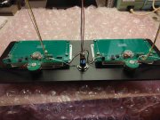
Note the Phoenix connector at the top of the WOA 1000C Amplifier Board. This 4-position connector has to face inward because the side of the Board is up against the side of the amplifier and the wires cannot exit. Don't ask me how I know this.

This is an updated picture of the Faceplate showing all the wiring except the Left and Right Output Level feeds to the meters. Those wires originate on the back of the amplifier. And notice I installed the 100K Goldpoint stepped attenuators, they just fit.
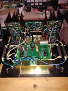
This is the Model ONE chassis almost fully wired. It has taken so long because I have measured each wire and documented the lengths so the Wire Run List is accurate. Joe has been great helping me along the way. This assembly is not for the feint of heart.
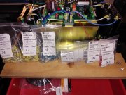
These are some of the terminals needed for the Model ONE assembly. I bought them 100 at a time to reduce unit cost. They are unique because they are the PIDG type that are used in aviation and military wiring assembly.
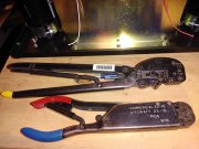
Here are the PIDG crimping tools. The larger one is for 12-10 AWG wire and the smaller one is for 16-14 and 22-18 AWG wire. You can tell by the color coded handles.
I am looking forward to Bring-up and testing soon.
The chassis wiring has been an adventure in changes. The latest revision is Rev R. There are now 115 wires listed in the Excel worksheet.
Note the Phoenix connector at the top of the WOA 1000C Amplifier Board. This 4-position connector has to face inward because the side of the Board is up against the side of the amplifier and the wires cannot exit. Don't ask me how I know this.

This is an updated picture of the Faceplate showing all the wiring except the Left and Right Output Level feeds to the meters. Those wires originate on the back of the amplifier. And notice I installed the 100K Goldpoint stepped attenuators, they just fit.

This is the Model ONE chassis almost fully wired. It has taken so long because I have measured each wire and documented the lengths so the Wire Run List is accurate. Joe has been great helping me along the way. This assembly is not for the feint of heart.

These are some of the terminals needed for the Model ONE assembly. I bought them 100 at a time to reduce unit cost. They are unique because they are the PIDG type that are used in aviation and military wiring assembly.

Here are the PIDG crimping tools. The larger one is for 12-10 AWG wire and the smaller one is for 16-14 and 22-18 AWG wire. You can tell by the color coded handles.

I am looking forward to Bring-up and testing soon.
J!m
Veteran and General Yakker
I have some of these connectors and they can be crimped with standard tools. (If anyone cares)
There is a second continuous ring around the typical split ring of the terminal under the insulation.
There is a second continuous ring around the typical split ring of the terminal under the insulation.
Hi Mark, those stepped attenuators may be prove to be a paint scraping fit alongside of the toroid housing when you put the faceplate in place.Here are some more pictures. I have the Model ONE almost fully wired except for attaching the Faceplate, that will be the last step.
The chassis wiring has been an adventure in changes. The latest revision is Rev R. There are now 115 wires listed in the Excel worksheet.
Note the Phoenix connector at the top of the WOA 1000C Amplifier Board. This 4-position connector has to face inward because the side of the Board is up against the side of the amplifier and the wires cannot exit. Don't ask me how I know this.
View attachment 79142
This is an updated picture of the Faceplate showing all the wiring except the Left and Right Output Level feeds to the meters. Those wires originate on the back of the amplifier. And notice I installed the 100K Goldpoint stepped attenuators, they just fit.
View attachment 79143
This is the Model ONE chassis almost fully wired. It has taken so long because I have measured each wire and documented the lengths so the Wire Run List is accurate. Joe has been great helping me along the way. This assembly is not for the feint of heart.
View attachment 79145
These are some of the terminals needed for the Model ONE assembly. I bought them 100 at a time to reduce unit cost. They are unique because they are the PIDG type that are used in aviation and military wiring assembly.
View attachment 79146
Here are the PIDG crimping tools. The larger one is for 12-10 AWG wire and the smaller one is for 16-14 and 22-18 AWG wire. You can tell by the color coded handles.
View attachment 79147
I am looking forward to Bring-up and testing soon.
I bypass my level controls on the amp control board using the jumpers provided and do not use the level pots (after I completed testing). They are decoration only. My preamp does that job, as it should.
mlucitt
Veteran and General Yakker
Joe, the Goldpoint stepped attenuators actually sit below the level of the VU meter movement case. The only impingement I have on the Transformer Cover are the wires that come off the Power Switch, they can easily be routed upward to meet the Power Control Board when the time comes to install the Faceplate.Hi Mark, those stepped attenuators may be prove to be a paint scraping fit alongside of the toroid housing when you put the faceplate in place.
I bypass my level controls on the amp control board using the jumpers provided and do not use the level pots (after I completed testing). They are decoration only. My preamp does that job, as it should.
I like the level controls to optimize the input impedance of the amplifier. I have found that around 50% volume, the 50K of the level controls and the 39K of the amplifier input loading combine to make make a beautiful musical tonality that harmonizes well with my low loss, low capacitance interconnects and my 100% copper-free power cable.
I think it is getting deep in here now...
Last edited:
Very, very deep Mark, time to put on my Wellies...Joe, the Goldpoint stepped attenuators actually sit below the level of the VU meter movement case. The only impingement I have on the Transformer Cover are the wires that come off the Power Switch, they can easily be routed upward to meet the Power Control Board when the time comes to install the Faceplate.
I like the level controls to optimize the input impedance of the amplifier. I have found that around 50% volume, the 50K of the level controls and the 39K of the amplifier input loading combine to make make a beautiful musical tonality that harmonizes well with my low loss, low capacitance interconnects and my 100 copper-free power cable.
I think it is getting deep in here now...
J!m
Veteran and General Yakker
100% copper free? Silver power cable?
That’s fancy.
That’s fancy.
mlucitt
Veteran and General Yakker
Oxygen free or copper free, it's the latest thing. You gotta have it.100% copper free? Silver power cable?
That’s fancy.
https://www.amazon.com/Studio-Reference-99-999-Silver-Power/dp/B00X68JZF4
Darn it, they are out of stock...
J!m
Veteran and General Yakker
Looks like a used one can be had for only $1400!
MarkWComer
Veteran and General Yakker
- Joined
- Nov 1, 2014
- Messages
- 3,520
- Location
- Gaston, SC
- Tagline
- Victim of the record bug since age five
There is a small group of people who say that trepanation has benefits…I need that cord like an additional hole in my head.
mlucitt
Veteran and General Yakker
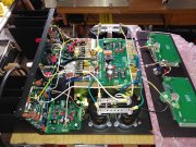
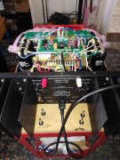
The White Oak Audio Model ONE Amplifier is compete! The delay was caused by not having two specific #10 16-14 AWG PIDG terminals for the Speaker Output Binding Post connections inside the amplifier. I received them from Mouser on Wednesday.
I have just started the 53-step Bring Up Instructions that I received from Joe earlier this week.
Here are some pictures of the finished product. After Bring Up, comes testing and some long-awaited enjoyment...

I have just started the 53-step Bring Up Instructions that I received from Joe earlier this week.
Here are some pictures of the finished product. After Bring Up, comes testing and some long-awaited enjoyment...


Pulpmillguy
Journeyman
Looking great! Can't wait to see the numbers, wish I could be there to hear that monster when you get it up and running. (Got a feeling it sounds a little better than my WOPL...just a little thoughThe White Oak Audio Model ONE Amplifier is compete! The delay was caused by not having two specific #10 16-14 AWG PIDG terminals for the Speaker Output Binding Post connections inside the amplifier. I received them from Mouser on Wednesday.
I have just started the 53-step Bring Up Instructions that I received from Joe earlier this week.
Here are some pictures of the finished product. After Bring Up, comes testing and some long-awaited enjoyment...
View attachment 79295
View attachment 79296
View attachment 79297
