The ultimate dual 500 "rising from the ashes" build

grapplesaw

Veteran and General Yakker
Joined
Aug 13, 2014
Messages
2,773
Location
Vancouver
Tagline
---
#41
I am sorry for the delay in answering your post. I just got back from the east coast where I visited with some of my relatives over the holidays.
I also visited with Mark Weiss http://www.basspig.com. My brother-in-law and I had a great time discussing audio (as well as other things) with Mark and will be back in 2016.

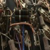
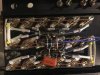
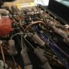
The terminal strips were made by HH Smith now Abbatron HH Smith (632 Arch Street, Meadville, PA 16335)

http://www.farnell.com/datasheets/1927258.pdf

http://www.abbatron.com/uploads/pdf/SD-3000 SER.pdf

http://www.spectron.net/Abbatron - Catalog.pdf see page 29

Phase Linear also used their terminal strips, speaker binding posts, strain reliefs, etc.

You should find the price from their dealers (not from the guy on ebay who wants $22.97) to be less than half of what you see on ebay for the items noted in the previous posts.

Ed
Thank you Ed. Great information here. The Abbatron cat is a treasure.
 

grapplesaw

Veteran and General Yakker
Joined
Aug 13, 2014
Messages
2,773
Location
Vancouver
Tagline
---
#42
Skycraft had them at $7.95 for 10 of them which is an excellent deal.
Thank you Joe. I had offered $7 for 10 pieces on on EBay but will cancel bid

Sky craft has then now for .34 cents each.

As we no longer have cents in Canada I do not know what to do!! This was all started when the Government removed cents from the Income tax forms may years ago and proving that they had no cense!! They re"cent"ly stopped make making the mighty penny to complete the full circle of Government incompetence in money management.

Happy New Year
Glen
 

grapplesaw

Veteran and General Yakker
Joined
Aug 13, 2014
Messages
2,773
Location
Vancouver
Tagline
---
#43
So after a great Breakfast of scrambled eggs and Bacon and two episodes of Star Wars myth busters
I shall return to the project

So we have agreed to
-replace to output jacks with the 30 amp three way binding posts
-full complementary output
- move bridge rectifier to sit above the relay bank olininating ac running across the width of the chassis
-reroute the B+/- to run straight to the backplane away from the AC feed.
-keep original front panel wires they are Silver plated 90c wires. Lot of work and parts to replace

Still at hand today

- replace stock .39 ohm emitter resistors with .33 ohm. My thinking here is standard part only.
- deal with ground circuit design for the input jacks. As per previous post.
- relocate the small transformer mounting location. This has AC running from RRear to Lfront of unit.

image.jpg

Sorry
This the shot

image.jpg
 
Last edited:

grapplesaw

Veteran and General Yakker
Joined
Aug 13, 2014
Messages
2,773
Location
Vancouver
Tagline
---
#45
Joe,

Thanks for the heads up. Their price is bar far the lowest of them all!
Perhaps now is the time to stock up.

It appears that they are now selling them for 35 cents each. I don't know what their shipping costs are, however.

http://www.skycraftsurplus.com/phenolicterminalstripsolderable.aspx

Ed
Hi Ed

If you have one there the original pieces please see if the dimensions from Skycraft are right. They do not add up in my book

Single-lugs
Non-grounding
Phenol Resin Support
Two Mounting Screw Points

Dimensions:
Metal Base: 2.55" (L) x 0.28" (W)
Mounting Hole Center to Center: 2.37"
Diameter of Mounting Hole: 0.15"
Maximum Height: 0.85"
Lug Center to Center Spacing: 0.42"
Lug Hole Size: 0.19" (H) x 0.11" (W)
 

oldphaser

Chief Journeyman
Joined
Sep 8, 2012
Messages
848
#46
Using .33 Ohm Versus Stock .39 ohm Emitter Resistors in a Phase Linear Dual 500/D-500

I am certainly no expert when it comes to "emitter degeneration", as it would be affected in a Dual 500/D-500, if you change the value of the stock .39 ohm resistors to .33 ohm.
Perhaps Joe or Lee could illuminate the subject a little better, before you make your final decision on using .33 ohm versus the stock .39 ohm resistors.


NOTE: Type in "emitter degeneration" on google and you will get a plethora of results.

Ed

 
Last edited:

oldphaser

Chief Journeyman
Joined
Sep 8, 2012
Messages
848
#47
Hi Ed

If you have one there the original pieces please see if the dimensions from Skycraft are right. They do not add up in my book

Single-lugs
Non-grounding
Phenol Resin Support
Two Mounting Screw Points

Dimensions:
Metal Base: 2.55" (L) x 0.28" (W)
Mounting Hole Center to Center: 2.37"
Diameter of Mounting Hole: 0.15"
Maximum Height: 0.85"
Lug Center to Center Spacing: 0.42"
Lug Hole Size: 0.19" (H) x 0.11" (W)

GOOD CATCH!

The center to center distance is critical.


The HH Smith's are 2.250".
The Skycraft's appear to be 2.37"

I also verified the center to center distance of the HH Smith's I have with my dial calipers.

This .120" difference will not allow you to screw into the holes that are currently tapped into the back of the heat-sink.

Ed
 

Gepetto

Administrator
Staff member
Joined
May 15, 2011
Messages
13,663
Location
Sterling, MA
Tagline
Old 'Arn Enthusiast
#48
GOOD CATCH!

The center to center distance is critical.


The HH Smith's are 2.250".
The Skycraft's appear to be 2.37"

I also verified the center to center distance of the HH Smith's I have with my dial calipers.

This .120" difference will not allow you to screw into the holes that are currently tapped into the back of the heat-sink.

Ed
I would ask Skycraft. I suspect it is possible someone there does not know how to measure.
 

laatsch55

Administrator,
Staff member
Joined
Jan 14, 2011
Messages
74,424
Location
Gillette, Wyo.
Tagline
Halfbiass...Electron Herder and Backass Woof
#49

Gepetto

Administrator
Staff member
Joined
May 15, 2011
Messages
13,663
Location
Sterling, MA
Tagline
Old 'Arn Enthusiast
#50
I am certainly no expert when it comes to "emitter degeneration", as it would be affected in a Dual 500/D-500, if you change the value of the stock .39 ohm resistors to .33 ohm.
Perhaps Joe or Lee could illuminate the subject a little better, before you make your final decision on using .33 ohm versus the stock .39 ohm resistors.


NOTE: Type in "emitter degeneration" on google and you will get a plethora of results.

Ed

I have standardized on 0.33 ohm emitter resistors everywhere. Make sure they are NOT wirewound (as WW resistors are inductive unless specially wound (rare)). Metal film or metal oxide are the type to use.
 

grapplesaw

Veteran and General Yakker
Joined
Aug 13, 2014
Messages
2,773
Location
Vancouver
Tagline
---
#52
I have standardized on 0.33 ohm emitter resistors everywhere. Make sure they are NOT wirewound (as WW resistors are inductive unless specially wound (rare)). Metal film or metal oxide are the type to use.
Thanks Joe
This was why I wanted to have them at .33 as well. I have 2 watt 5% and 3 watt 2%
MOX2CT631RR33J & MOSX3CT631RR33G.

I will use the 3 watt metal oxide
 

grapplesaw

Veteran and General Yakker
Joined
Aug 13, 2014
Messages
2,773
Location
Vancouver
Tagline
---
#53
The replacement starts

#12 collector wire installed. I have #14 for the base wire. Went to up some ferric beads on it but the hole is to small. After breaking one and being satisfied it would not go on I have to decide proceeding with the #14 without beads and using snap on type later if they are needed. Or go to the store and get some #16 solid core wire.

Any one used the snap on ones??

image.jpg
image.jpg
 
Last edited:

grapplesaw

Veteran and General Yakker
Joined
Aug 13, 2014
Messages
2,773
Location
Vancouver
Tagline
---
#55
You've had a busy day if the left channel is done....
Thanks Lee
No such luck that is the old one there for you reference Cleaned the heat sink and bolted in one Chanel bases.

This all I got done.

image.jpg

image.jpg

image.jpg


Before shot

image.jpg

We went Mom's for visit and chores. She is 96 still living on her own
 
Last edited:

grapplesaw

Veteran and General Yakker
Joined
Aug 13, 2014
Messages
2,773
Location
Vancouver
Tagline
---
#58
Some headway today

The old one

image.jpg image.jpg image.jpg

The First new backplate done. The second should be a little faster.

image.jpg image.jpg image.jpg

Cleaned up the Fuse holders and started removing old banana plugs. These were not original. The holes are oversized from stock. I will have to drill them some more to fit the heaven binding posts. No option now.


Check our how to run your equipment without fuses. Who knew!!

image.jpg image.jpg
 

Attachments

Last edited:

grapplesaw

Veteran and General Yakker
Joined
Aug 13, 2014
Messages
2,773
Location
Vancouver
Tagline
---
#59
Spent several hours on mapping out wiring for full comp setup today. I have found that many errors are the 700 comp drawings. I will need to modify the out put stage on the cp boards and now have arranged all the wiring ( I hope) I found that the original wiring on this unit was different to the drawings and my other units. I am now sure this was a proto type unit.


One wire to decide on is the sensor for the high frequency unit. It was on the emitter side between the transistor and the emitter resistor. On B- side Haw the these are inverted I will move the wire to this same layout on the full comp set up.

image.jpg
 
Last edited:

laatsch55

Administrator,
Staff member
Joined
Jan 14, 2011
Messages
74,424
Location
Gillette, Wyo.
Tagline
Halfbiass...Electron Herder and Backass Woof
#60
That's a lot of point to point wiring Glen, and you're making it look good! Nice job Bud....
 
Top