
Hi Guys,
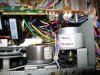
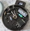
Tonight I dug into my Tascam 112B and have a few questions. I believe the capstan motor is trashed but have a couple questions:
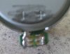
1)Does anyone have a clue as to what the color code of the capstan motor wires are? The motor is a Sanyo marked with SHW2L, 00-0206A. It's a CCW rotation motor and I believe it is 12 volts. There are two pairs of wires Orange and orange with black marks, the other pair is yellow and yellow with orange marks.
2)The yellow pair runs to a PCB labeled PCB 52101958-00, Teac, AP42S. This looks like a power supply board as the large filter caps have roughly 17 volts across them. Would anyone have a schematic for this board??? There looks to be a sense resistor of about 10 ohms on the high side but I don't understand the return portion of the circuit. The are a couple other resistors and caps on the pcb but not exactly sure what their purpose is at the moment.
3)The orange pair runs to the area of the pitch control switch and pot.
4)My guess is two wires are power so are the other two wires an encoder or sometype of feedback?
5)I would test the motor stand alone but really would like to understand the wiring scheme before letting the magic smoke out.
Does anyone know of a source for the above motor or something which may work? I searched around the internet a bit but did not find much of anything.
Does anyone have a schematic which could help?
Thanks,
Robert
Tonight I dug into my Tascam 112B and have a few questions. I believe the capstan motor is trashed but have a couple questions:
1)Does anyone have a clue as to what the color code of the capstan motor wires are? The motor is a Sanyo marked with SHW2L, 00-0206A. It's a CCW rotation motor and I believe it is 12 volts. There are two pairs of wires Orange and orange with black marks, the other pair is yellow and yellow with orange marks.
2)The yellow pair runs to a PCB labeled PCB 52101958-00, Teac, AP42S. This looks like a power supply board as the large filter caps have roughly 17 volts across them. Would anyone have a schematic for this board??? There looks to be a sense resistor of about 10 ohms on the high side but I don't understand the return portion of the circuit. The are a couple other resistors and caps on the pcb but not exactly sure what their purpose is at the moment.
3)The orange pair runs to the area of the pitch control switch and pot.
4)My guess is two wires are power so are the other two wires an encoder or sometype of feedback?
5)I would test the motor stand alone but really would like to understand the wiring scheme before letting the magic smoke out.
Does anyone know of a source for the above motor or something which may work? I searched around the internet a bit but did not find much of anything.
Does anyone have a schematic which could help?
Thanks,
Robert

")