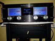
It sounds like you need to get a bigger dummy load. And enough to do (2) channels (both channels driven) of at least at 500 watts per channel into 8 ohms.
I have several dedicated dummy loads:
1.) 1000 watts a channel at 4 ohms (total of 2,000 watts)
2.) 1000 watts a channel at 8 ohms (total of 2,000 watts)
I can easily handle a Phase Linear Dual 500/D-500 into either 8 or 4 ohms both channels driven.
I also have a box full of Dale NH-250's (250 watt resistors) at 2, 4 and 8 ohms. I plan on making a dedicated 2 ohm load at 1000 watts per channel as well.
I also perform damping factor/ratio measurements. Phase Linear's spec for the 700 series amps is 1000:1 at 1kHz into a 8 ohm load.
You will find lower damping ratio figures with a DCP relay installed. Typically around 200:1 instead of 1000:1.
NOTE: Damping factor is the speaker impedance (8 Ω) divided by the amplifier output impedance (i.e. .008Ω). The test method noted below is another (more common) way to derive the damping factor. In some circles it is known as the Crown method.
Bob Carver indicated that he used a Vector Voltmeter to measure damping factor and that he did not like other methods. I have yet to see what model of Vector Voltmeter he was using or his measurement method/techniques. The HP Vector Voltmeters during the era these amps were made only go down to 1 ohm.
NOTE: Phase Linear 700 series 1 Owner’s Manual (Edmonds, WA revision) states:
“
A high resolution vector voltmeter is required to accurately measure damping. Damping factor is defined as Z1/Zi = Vo-V1) and must be computed by directly determining the quantity (Vo-V1). Any attempt to measure damping by using an abnormal load, or by driving the amplifier with an active current or voltage source will yield invalid results. Determine the quantity (Vo-V1), compute the damping ratio Z1/Zi, and verify that it exceeds 1000:1 for all frequencies below 200 cycles.” NOTE: Later documents had the damping factor at 1kHz.
Other methods used impedance bridges and back-feeding. As with the case with impedance bridges; they would measure the output voltage, insert some resistance across the output and at a point when the voltage was exactly 1/2 the value, the impedance bridge resistance would be equal to the output impedance. This is a bit difficult to do when you consider measuring down to .008 ohms. In some cases, I have seen, there may be a value of resistance say ten times larger than nominal and some math was performed to derive the output impedance. Crown had an earlier method in one of their amplifier service manuals whereby they ran a signal out from one channel back into the output of the other channel.
Audio Power Amplifiers part 2 by Bob Cordell pg 489 states:
Measuring Damping Factor
“….
Damping factor is defined as the ratio of 8 Ω to the output impedance of an amplifier. An amplifier whose output impedance is 0.16Ω will have a damping factor of 50. The output impedance of the amplifier forms a voltage divider with the speaker load impedance, creating attenuation between the idealized output and the actual output. The damping factor can be inferred by measuring the amplifier frequency response under no-load and with a known-load. This is a fairly crude approach.”
“A better approach is to inject a signal current into the output of the amplifier and measure the voltage. Such an arrangement is shown in Figure x. This can be done by back-feeding from another amplifier through a 100-Ω 2-W resistor. The back feeding amplifier is set to an output level of 10V RMS. This will create a “probe” signal current of approximately 100 mA RMS. The voltage across the output terminals of the amplifier under test (AUT) is then measured with an AC voltmeter. A 10-mV reading will correspond to an output impedance of 100 mΩ, which in turn corresponds to a DF of 80. The test frequency should be swept across the audio band to obtain a plot of output impedance versus frequency.”
“It is wise and instructive to view the signal at the output terminals on an oscilloscope as well. First, make sure that the wideband noise from the amplifier is not dominating the reading. If it is, insert a 100-kHz low-pass filter ahead of the AC voltmeter. Secondly, make sure that hum from the AUT is not dominating the reading. If it is, insert a high pass filter ahead of the AC voltmeter and measure DF only above 1 kHz.”
“Finally, the oscilloscope waveform may unmask some crossover distortion whose percentage has been magnified by the DF. The signal at the output terminals of the AUT can also be viewed with a spectrum analyzer. This is especially useful when the damping factor is very high and the fundamental of the probing signal is very small.”
NOTE: My tests were performed with a single channel driven under the following conditions: using Dale NH-250 resistors with (2) 12” 14Ga leads connected directly to the amplifier. Pomona B-12 leads were connected from the amplifier to my DMM. The output of the signal generator was also monitored with another DMM. I also monitored the Variac output voltage with and without a 8 ohm load with yet another DMM. (Tests were performed with an 8 ohm load and the Variac allowed to sag (noting the results) and by adjusting the Variac to maintain 120.0V with the 8 ohm load and noting those results as well.) All DMM's were the same manufacturer and model.
DF = E no load/ (E no load – E loaded)
If E no load = 53 volts
And
E loaded = 52.947 volts
DF = 53/.053
DF = 1000
NOTE: I also performed measurements at 0dB (rated output), -3dB, -6dB and -10dB to see what effects loading the amplifier would have.
An additional article on damping factor:
Performance-Check Your Amp and Preamp Part II Maximum Output Power, Power Bandwidth, Damping Factor, Preamp Maximum Input and Output Voltage, Crosstalk and Separation by M. J. Salvati Audio March 1984 pgs 42-48
Ed


