Sutt's "Fugly One" WOPL Transformation

oldphaser

Chief Journeyman
Joined
Sep 8, 2012
Messages
845
A Phase Linear 700 series II amplifier; single channel driven at 1kHz into 8 ohms at 1% THD should be around 510-515 watts. Both channels driven at 1kHz into 8 ohms at 1% THD should be around 440 watts. Both channels driven at 1kHz into a 4 ohm load at 1% THD will be close to 700 watts. NOTE: According to my Monster Power AVS2000 display indication; under the conditions noted above for both channels driven into 8 ohms, the current draw is around 9.82 amps, and for 4 ohms is around 16 amps. NOTE: For both channels driven into a 4 ohm load you will need to increase the line fuse from 10 amps to at least 15 amps and the line supply cord should be 15 Amps as well. (NOTE: I have seen some modified 700 series amps with 10A line cords installed.) Fortunately the ABC15 fuse I used did not blow during this round of tests. The AGX fuses will also need to be increase from 5 amp to 8 amps as well. When testing at 4 ohms, particularly at 20kHz you run the risk of blowing the Zobel network resistors which are (2) 2 watt 10 ohm resistors in parallel for an effective 5 ohms. Clair Brothers discovered this themselves and insisted that Phase Linear use 5 ohm 50 watt resistors.
 

oldphaser

Chief Journeyman
Joined
Sep 8, 2012
Messages
845
With regards to performing signal-to-noise ratio measurements:

IHF-A-202 (1978) "the voltmeter shall have full wave average rectifying characteristics and shall be calibrated to read the rms voltage of a sine wave..."

Currently I am using (2) NF Corporation Autoranging AC Millivoltmeter/Noise Meter's. It has a variety of weighting filters: Flat (unweighted) A, C, DIN Audio, CCIR ARM. It also has True RMS, Average and Quasi-Peak detection. Range: -90 to +40dB)


Previously I used several Leader LMV-185A 2 Channel AC Millivoltmeter's (-60dB to +50dB). I am only using this for volume pot tracking these days . "It responds to the average value of the input signal but is calibrated to indicate the r.m.s. value of a sine wave".

Here is the A weighting circuit schematic for those who would like to add this to their voltmeter: A weighting circuit.png


Additionally, here is a link to Rod Elliott's active "A" weighting filter (see figure 3):
http://sound.whsites.net/project17.htm

Hewlett Packard Application Note 60 "Which AC Voltmeter?":
http://hpmemoryproject.org/an/pdf/an_60.pdf


Ed
 

jbeckva

Admin/Server Dude MAA Guy
Staff member
Joined
Jun 11, 2010
Messages
6,842
Location
Powhatan, Virginia, United States
Tagline
WassupYa Mang?
Thanks for the info, Ed. I'd retest THIS build (I'll actually test my own "Franky" here shortly), but two things.. first is that I come to find out that I did in one of the dummy loads (cheap china stuff I guess LOL). I was adding length to the wires on the load after testing (making it easier to hook everything up) when I checked the resistance - not 8 ohms more like 2K or so. Tugged on one of the leads and out it popped.

Second.. Sutt's chompin' at the bit LOL. Suffice to say tho, the amp's been through heck and should last a long time. If not, then it's warranted for as long as I can hold a soldering iron.

Look for another thread that will detail the kind of test automation experiments I'm doing. It was really REALLY cool to apply some mathematics knowledge when working on the "program". I had it first calculating the overall voltage gain by starting at a relatively low input / measuring the output. Then when I had that figure I was able to write a sub to set the output voltage to exactly what I wanted. After that and given the good ole ohm's law (P=SQRT(R x E)), I was able to explicitly specify the power level desired - and based solely on the formulas it actually proved out when measuring the results! How cool is that? If I wanted to output 5 watts, I would enter 5 and press a button!

Yeah yeah, baby steps LOL. I do have a WOPL 500 in the other room, so when I get that load replaced I can continue playing. Well.. I'll likely not wait haha.
 

jbeckva

Admin/Server Dude MAA Guy
Staff member
Joined
Jun 11, 2010
Messages
6,842
Location
Powhatan, Virginia, United States
Tagline
WassupYa Mang?
.. LOL clarifying that formula.. Since we know the wattage needed (P), and the resistance (8 ohms), we solve for voltage required (E). And also apply the measured voltage ratio when doing so. Well, something like that.. coffee is kicking in, but not quite yet. :thumbright:
 

oldphaser

Chief Journeyman
Joined
Sep 8, 2012
Messages
845
It sounds like you need to get a bigger dummy load. And enough to do (2) channels (both channels driven) of at least at 500 watts per channel into 8 ohms.

I have several dedicated dummy loads:
1.) 1000 watts a channel at 4 ohms (total of 2,000 watts)
2.) 1000 watts a channel at 8 ohms (total of 2,000 watts)

I can easily handle a Phase Linear Dual 500/D-500 into either 8 or 4 ohms both channels driven.

I also have a box full of Dale NH-250's (250 watt resistors) at 2, 4 and 8 ohms. I plan on making a dedicated 2 ohm load at 1000 watts per channel as well.


I also perform damping factor/ratio measurements. Phase Linear's spec for the 700 series amps is 1000:1 at 1kHz into a 8 ohm load.

You will find lower damping ratio figures with a DCP relay installed. Typically around 200:1 instead of 1000:1.

NOTE: Damping factor is the speaker impedance (8 Ω) divided by the amplifier output impedance (i.e. .008Ω). The test method noted below is another (more common) way to derive the damping factor. In some circles it is known as the Crown method.

Bob Carver indicated that he used a Vector Voltmeter to measure damping factor and that he did not like other methods. I have yet to see what model of Vector Voltmeter he was using or his measurement method/techniques. The HP Vector Voltmeters during the era these amps were made only go down to 1 ohm.

NOTE: Phase Linear 700 series 1 Owner’s Manual (Edmonds, WA revision) states:

A high resolution vector voltmeter is required to accurately measure damping. Damping factor is defined as Z1/Zi = Vo-V1) and must be computed by directly determining the quantity (Vo-V1). Any attempt to measure damping by using an abnormal load, or by driving the amplifier with an active current or voltage source will yield invalid results. Determine the quantity (Vo-V1), compute the damping ratio Z1/Zi, and verify that it exceeds 1000:1 for all frequencies below 200 cycles.” NOTE: Later documents had the damping factor at 1kHz.


Other methods used impedance bridges and back-feeding. As with the case with impedance bridges; they would measure the output voltage, insert some resistance across the output and at a point when the voltage was exactly 1/2 the value, the impedance bridge resistance would be equal to the output impedance. This is a bit difficult to do when you consider measuring down to .008 ohms. In some cases, I have seen, there may be a value of resistance say ten times larger than nominal and some math was performed to derive the output impedance. Crown had an earlier method in one of their amplifier service manuals whereby they ran a signal out from one channel back into the output of the other channel.

Audio Power Amplifiers part 2 by Bob Cordell pg 489 states:
Measuring Damping Factor

“….Damping factor is defined as the ratio of 8 Ω to the output impedance of an amplifier. An amplifier whose output impedance is 0.16Ω will have a damping factor of 50. The output impedance of the amplifier forms a voltage divider with the speaker load impedance, creating attenuation between the idealized output and the actual output. The damping factor can be inferred by measuring the amplifier frequency response under no-load and with a known-load. This is a fairly crude approach.”

“A better approach is to inject a signal current into the output of the amplifier and measure the voltage. Such an arrangement is shown in Figure x. This can be done by back-feeding from another amplifier through a 100-Ω 2-W resistor. The back feeding amplifier is set to an output level of 10V RMS. This will create a “probe” signal current of approximately 100 mA RMS. The voltage across the output terminals of the amplifier under test (AUT) is then measured with an AC voltmeter. A 10-mV reading will correspond to an output impedance of 100 mΩ, which in turn corresponds to a DF of 80. The test frequency should be swept across the audio band to obtain a plot of output impedance versus frequency.”

“It is wise and instructive to view the signal at the output terminals on an oscilloscope as well. First, make sure that the wideband noise from the amplifier is not dominating the reading. If it is, insert a 100-kHz low-pass filter ahead of the AC voltmeter. Secondly, make sure that hum from the AUT is not dominating the reading. If it is, insert a high pass filter ahead of the AC voltmeter and measure DF only above 1 kHz.”

“Finally, the oscilloscope waveform may unmask some crossover distortion whose percentage has been magnified by the DF. The signal at the output terminals of the AUT can also be viewed with a spectrum analyzer. This is especially useful when the damping factor is very high and the fundamental of the probing signal is very small.”


NOTE: My tests were performed with a single channel driven under the following conditions: using Dale NH-250 resistors with (2) 12” 14Ga leads connected directly to the amplifier. Pomona B-12 leads were connected from the amplifier to my DMM. The output of the signal generator was also monitored with another DMM. I also monitored the Variac output voltage with and without a 8 ohm load with yet another DMM. (Tests were performed with an 8 ohm load and the Variac allowed to sag (noting the results) and by adjusting the Variac to maintain 120.0V with the 8 ohm load and noting those results as well.) All DMM's were the same manufacturer and model.

DF = E no load/ (E no load – E loaded)

If E no load = 53 volts

And

E loaded = 52.947 volts

DF = 53/.053

DF = 1000


NOTE: I also performed measurements at 0dB (rated output), -3dB, -6dB and -10dB to see what effects loading the amplifier would have.

An additional article on damping factor:
Performance-Check Your Amp and Preamp Part II Maximum Output Power, Power Bandwidth, Damping Factor, Preamp Maximum Input and Output Voltage, Crosstalk and Separation by M. J. Salvati Audio March 1984 pgs 42-48


Ed
 
Last edited:

oldphaser

Chief Journeyman
Joined
Sep 8, 2012
Messages
845
When somebody warranties an amplifier, what does the warranty cover? Does it include some quality controls, i.e. meeting some published specs? Or is it against catastrophic failure?
 

ksrigg

Chief Journeyman
Joined
Jul 28, 2011
Messages
1,451
Location
Wise, Virginia
When somebody warranties an amplifier, what does the warranty cover? Does it include some quality controls, i.e. meeting some published specs? Or is it against catastrophic failure?
I have had one WOPL malfunction in the last 6 years or so (bad storage caps), and it was repaired by the builder, no questions asked. I now own 6 400 WOPLs and 4 700B WOPLS.... My original PL 400 blew up no fewer than 6 or 7 times in a two year time-frame, taking my speakers with it and I had to pay to have both the speakers replaced and the amp repaired every single time. No comparison on warranty...much less stability and performance from the original PL..
 

Gepetto

Administrator
Staff member
Joined
May 15, 2011
Messages
13,473
Location
Sterling, MA
Tagline
Old 'Arn Enthusiast
I have had one WOPL malfunction in the last 6 years or so (bad storage caps), and it was repaired by the builder, no questions asked. I now own 6 400 WOPLs and 4 700B WOPLS.... My original PL 400 blew up no fewer than 6 or 7 times in a two year time-frame, taking my speakers with it and I had to pay to have both the speakers replaced and the amp repaired every single time. No comparison on warranty...much less stability and performance from the original PL..
You nailed it Sutton...
 

ksrigg

Chief Journeyman
Joined
Jul 28, 2011
Messages
1,451
Location
Wise, Virginia
Just for clarity, my original PL 400 was bought new in the early 70's and was my amp through college. The speakers were Watkins WS-1. I bought the amp from Mr. Toad's Sound Concepts, and the speakers from Watkins Stereo Center. Every time the amp blew, Watkins would blame the amp, and Toad's would blame the speakers (wide swings in impedance, they said). I did eventually put fuses in my speaker circuit to stop blowing speakers every time the amp ran away..After all the troubles, I bought Bose 901's but the amp continued to blow. I finally traded the PL 400 and got a Luxman M-4000 and Luxman C-1000 preamp. I had no further issues with the amp blowing up and taking speakers with them. Everyone at Watkins and Toad's knew me well!!! I still have the Lux gear and the Watkins speakers.....in my "inventory", but rarely use them.. Phase Linear always had a special place in my heart and when I discovered Pheonix and all the work that had been done by Joe and Lee and Don, and others, I had to give it another try...and I am glad I did. I sold all my Bryston gear and went all in... I think the improvements that have been made are fabulous. Got to hand it to Bob Carver, but the original design had some major problems....

Jerry, the WOPL is "out for delivery"....so I should get her today!!

I also ordered some knobs from China...we will see how they fit.....and look....

Thank you so much for building her.
 

Northwinds

Veteran and General Yakker
Joined
Mar 18, 2013
Messages
7,543
Location
Coventry, CT
Tagline
Fondler errrr... fan of all Nav's avatars
A Phase Linear 700 series II amplifier; single channel driven at 1kHz into 8 ohms at 1% THD should be around 510-515 watts. Both channels driven at 1kHz into 8 ohms at 1% THD should be around 440 watts. Both channels driven at 1kHz into a 4 ohm load at 1% THD will be close to 700 watts. NOTE: According to my Monster Power AVS2000 display indication; under the conditions noted above for both channels driven into 8 ohms, the current draw is around 9.82 amps, and for 4 ohms is around 16 amps. NOTE: For both channels driven into a 4 ohm load you will need to increase the line fuse from 10 amps to at least 15 amps and the line supply cord should be 15 Amps as well. (NOTE: I have seen some modified 700 series amps with 10A line cords installed.) Fortunately the ABC15 fuse I used did not blow during this round of tests. The AGX fuses will also need to be increase from 5 amp to 8 amps as well. When testing at 4 ohms, particularly at 20kHz you run the risk of blowing the Zobel network resistors which are (2) 2 watt 10 ohm resistors in parallel for an effective 5 ohms. Clair Brothers discovered this themselves and insisted that Phase Linear use 5 ohm 50 watt resistors.
Ed, do I need a 15A cord? You were last to look at it
 

oldphaser

Chief Journeyman
Joined
Sep 8, 2012
Messages
845
Ed, do I need a 15A cord? You were last to look at it

I can't recall specifically looking at the power cord on your amp.
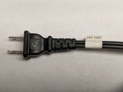
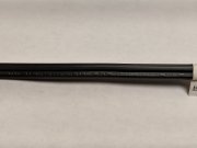
However, if it looks anything like the one in the photos below, then yes the power cord should be replaced with a 15A (16AWG) non-polarized power cord.

The 10A power cords may in all likelihood be on other WOPL amps out there.
If the 10A 125V tag is missing from the power cord, look for the following on the side of the power cord:
"YUNG LI. (UL) E241374 SPT-2 2/C 18AWG(0.824mm2) 105°C 300V VW-1"

Ed 10A Power Cord photo 1.jpg 10A Power Cord Photo 2.jpg
 

ksrigg

Chief Journeyman
Joined
Jul 28, 2011
Messages
1,451
Location
Wise, Virginia
The amp is really amazing. I've been listening to it for hours.

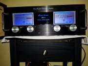
I also love the look. The black face, the silver rack handles, the silver bezels, the blue LEDs.... all look great together.

Also, have the caps on the light board been beefed up? I have noticed no dimming of the meter lights with strong current swings in the music, and I have noticed dimming on earlier PL amps...

The main thing is the beefy sound of the amp. It never strains at all, no matter the music or amount of bass. Just clarity...it just shimmers, and slams....at the same time. Just an awesome amp...

As has been said before, I use to think the 400 was sweeter, and just a better sounding amp....but not near the power......Now, I think the 700b sounds just as sweet, if not sweeter and more articulate.

Jerry, I see why you had a hard time NOT listening to her...and packing her up... Man, this is NICE!!!!!!!

Thanks again..
 

Attachments

Last edited:

Gepetto

Administrator
Staff member
Joined
May 15, 2011
Messages
13,473
Location
Sterling, MA
Tagline
Old 'Arn Enthusiast
Hi Sutton
Same filter caps on the PL700 and PL400 from day one. The 700 has more room than the 400 so larger caps went in for the 700 although the 400 are quite large too, you can lose power for a second or so on the 700 and the LEDs still hang in there.
 

Northwinds

Veteran and General Yakker
Joined
Mar 18, 2013
Messages
7,543
Location
Coventry, CT
Tagline
Fondler errrr... fan of all Nav's avatars
I can't recall specifically looking at the power cord on your amp.
However, if it looks anything like the one in the photos below, then yes the power cord should be replaced with a 15A (16AWG) non-polarized power cord.

The 10A power cords may in all likelihood be on other WOPL amps out there.
If the 10A 125V tag is missing from the power cord, look for the following on the side of the power cord:
"YUNG LI. (UL) E241374 SPT-2 2/C 18AWG(0.824mm2) 105°C 300V VW-1"

Ed View attachment 34162 View attachment 34163
I will try and look Ed, I have to pull my whole cabinet away from the wall to get at the cord

Sorry I missed you call, maybe we can speak during the week
 

Bradrock

Veteran and General Yakker
Joined
Jun 7, 2017
Messages
1,563
Location
Alton Mo.
Tagline
---I run with Scissors
I'm so jealous. I need get off my ass & do something about it. I have a beautiful 700b sitting here that Lee sold me two years ago & I've not touched it yet. Nor the 3 400's gathering dust.
What a slacker I am.
 

ksrigg

Chief Journeyman
Joined
Jul 28, 2011
Messages
1,451
Location
Wise, Virginia
Yes Sir, you need to get started. It is a big investment, but you won't find anything commercially available that even comes close. It sound like you have the amps you will need for a really nice 5.1 or 7.1 system... You will wonder why you didn't do it sooner after you get the first amp finished. Go for the 700b first! You will be amazed. I think the amps are only limited by the speakers you have......and the room....and the sources.....and the preamp or processor..
 
Top